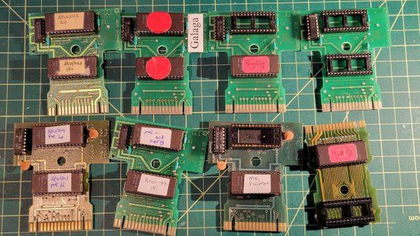
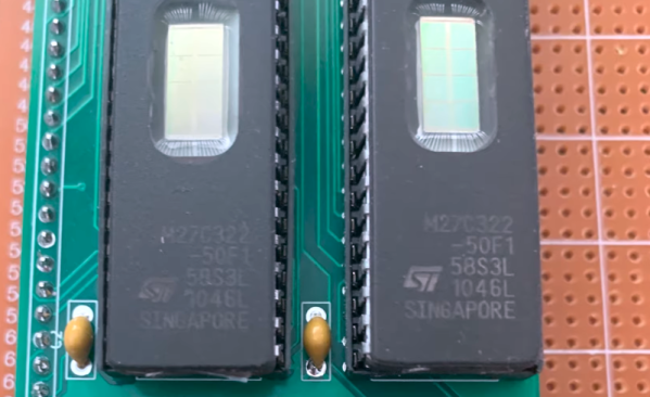
EPROMs, those UV-erasable memory chips of the 80s and 90s, once played a crucial role in countless electronic devices. They’ve become relics of a bygone era, but for enthusiasts of vintage electronics, the allure of these light-sensitive devices remains strong. Today, we’re diving into [Kevin Osborn]’s nostalgic journey as he uncovers the secrets of old EPROMs loaded with Atari 7800 code.
[Kevin] used to work at General Computer Company, which produced the Atari 7800 and several games for the system. Thus, he had a handful of old carts and development EPROMs sitting up in his attic along with an old console. Recently, he decided to try and uncover what was on the EPROMs and begun an investigation. They wouldn’t run in his Atari, and he quickly realized why: the EPROMs weren’t cryptographically signed, so the system wouldn’t load them. Continue reading “Working With Old High-Voltage EPROMs Is Fussy”→
Generating video signals is an exercise in periodicity. After all, an old-fashioned CRT just scans at a certain horizontal frequency and refreshes the entire screen each time it starts over. VGA is made to drive this technology. An EPROM chip can easily generate repeating patterns when driven by a counter at a known frequency.
As you might expect, there were a few software glitches to work out, but in the end, the circuit did its job, displaying a fixed image on a VGA monitor.
If you haven’t run into [Matt] before, he has a complete series on how he built a “wire-by-wire” Apple II clone. We will warn you, though. Don’t click on the link unless you have some spare time. The 18 videos take over two hours to work through, but there is some beautiful prototyping and a lot of good information in them.
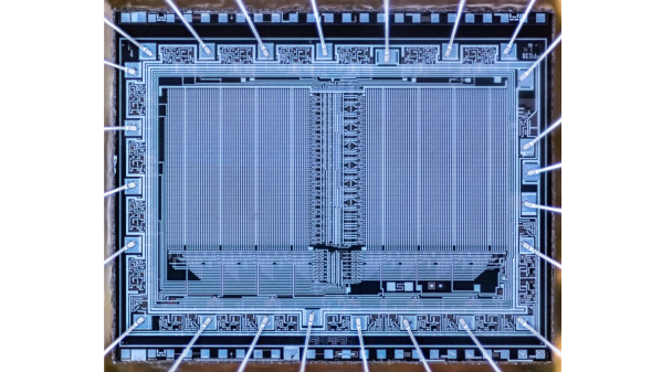
An article on the history of EPROMs in the Soviet Union by [Vladimir Yakovlev] over at The CPU Shack Museum caught our attention. It is part one of a series on the topic, and walks you through the earliest Soviet EPROMs families.
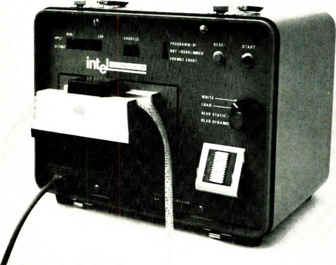
Early EPROM programmer using punched paper tape (Intel, Electronics Magazine 1971)
The first of which, from the 1970s, is the K505RR1 developed and manufactured in Kyiv, equivalent to the first-generation Intel 1702A. It could hold 2048 bits, organized as 256×8, and offered a whopping 20 reprogramming cycles and data retention of 5000 hours.
The narrative proceeds to introduce several subsequent generations, design facilities, manufacturing techniques, and representative chip examples. A few tidbits — unlike Western EPROMs, the Soviets managed to put quartz windows in plastic packages (see the KP573 family).
In addition to the common gray or white, they also used different terracotta colored ceramic packages. An odd ceramic flat-pack EPROM is shown, and also some EPROMs whose dies have been painted over and re-badged as OTP chips.
Intel began producing EPROMs in 1971 as reported by the inventor, Intel’s Dov Frohman-Bentchkowsky, in Electronics Magazine’s 10 May edition (pg 91). We learned, amongst other things, that the 1701 did not have a quartz window, but could still be erased by exposure to X-rays. A friendly word of warning — browsing electronics advertisements from 50 years ago can easily consume your entire morning.
Once the package is sealed, information can still be erased by exposing it to X radiation in excess of 5×10⁴ rads, a dose which is easily attainable with commercial X-ray generators.
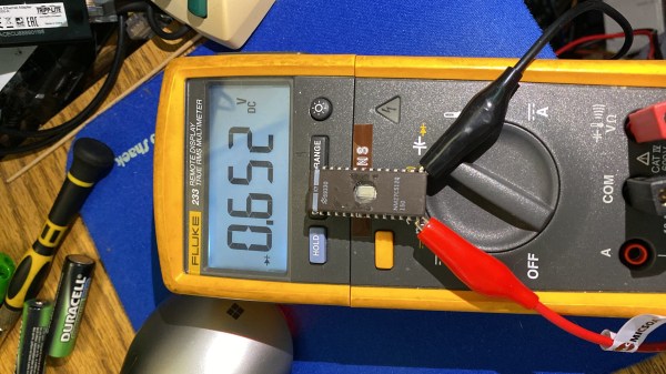
[Jason P], evidently an enjoyer of old reliable laser printing tech, spilled a drink (nitter) onto his Panasonic KX-P5400 SideWriter. After cleanup, everything worked fine — except that the PSU’s 5 V became 6.5 V during the accident, and the EPROM with LocalTalk interface firmware died, connection between VCC and GND seemingly interrupted inside the chip. Understandably, [Jason] went on Twitter, admitted the error of his ways, and sheepishly asked around for EPROM dumps.
Instead, [Manawyrm] wondered — would the chip have anti-ESD body diodes from GND to IO pins, by any chance? A diode mode multimeter check confirmed, yes! It was time for an outlandish attempt to recover the firmware. [Manawyrm] proposed that [Jason] connect all output pins but one to 5 V, powering the EPROM through the internal VCC-connected body diodes – reading the contents one bit at a time and then, combining eight dumps into a single image.
After preparing a TL866 setup, one hour of work and some PHP scripting later, the operation was a success. Apparently, in certain kinds of cases, dead ROM chips might still tell their tales! It’s not quite clear what happened here. The bond wires looked fine, so who knows where the connection got interrupted – but we can’t deny the success of the recovery operation! Need a primer on dumping EPROMs that are not dead? Here you go.
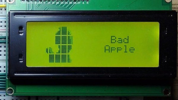
The Bad Apple!! video with its silhouette animation style has long been a staple graphics demo for low-end hardware, a more stylish alternative to the question “Will it run DOOM?”. It’s normal for it to be rendered onto a screen by a small microcomputer or similar but as [Ian Ward] demonstrates in an unusual project, it’s possible to display the video without any processor being involved. Instead he’s used a clever arrangement involving a 32K byte EPROM driving a HD44780-compatible parallel alphanumeric LCD display.
While 32K bytes would have seemed enormous back in the days of 8-bit computing, even when driving only a small section of an alphanumeric LCD it’s still something of a struggle to express the required graphics characters. This feat is achieved by the use of a second EPROM, which carries a look-up table.
It’s fair to say that the result which can be seen in the video below the break isn’t the most accomplished rendition of Bad Apple!! that we’ve seen, but given the rudimentary hardware upon which it’s playing we think that shouldn’t matter. Why didn’t we think of doing this in 1988!
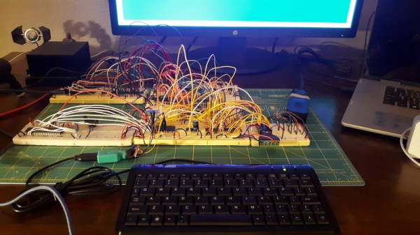
If you’ve ever worked on a system that loads its software from a ROM or EPROM, you know how much of a hassle it can be to make frequent changes to the code. Pulling the chip, flashing it, and sticking it back into the socket each time you change a line isn’t anyone’s idea of a good time. Which is why [Nick Bild] has come up with the PicoROM, a way to emulate a ROM chip using the Raspberry Pi Pico.
With the Pi Pico standing in for the original ROM, updating firmware takes a fraction of the time and doesn’t require you to actually disconnect any of the hardware. [Nick] had done something similar with FPGAs in the past, but the far cheaper and easier to work with Pi Pico makes this version particularly appealing. The secret to getting it to work is the overclocking potential of the Pico, which he says has been pushed to 400 MHz for this particular application.
PicoROM on a breadboard.
The downside is that you can’t access the Pico’s onboard flash when the chip is running that fast. To get around that limitation, all of the code is loaded into the microcontroller’s RAM. With a healthy 264 KB of memory this isn’t really a problem when emulating 32 KB chips, but [Nick] says his method would quickly fall apart for larger ROMs.
Beyond the Pi Pico itself, [Nick] is using a trio of 74LVC245AN 8-bit logic level shifters so the chip can talk to the 5 V logic of his homebrew 6502 computer. With everything wired up on a simple breadboard, PicoROM has no trouble serving up the operating system as it hums along at 2 MHz.
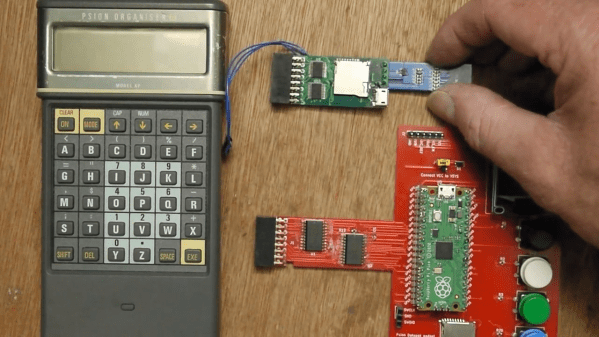
Remember the Psion Organiser? If you do, chances are you were an early adopter, as the 8-bit pocket computer had its heyday in the mid-1980s. Things have come a long way since then, of course, but just how far is illustrated nicely by the fact that a Raspberry Pi Pico can stand in for the Psion’s original memory packs.
Like many of the early attempts at putting a computer in your pocket, the Psion II had removable modules, which were dubbed “Datapaks”. The earliest versions of the Datapaks were little more than an EPROM chip on a small PCB, and the technical limitations of the day plus the quirky way of addressing the memory made it possible for [Amen] to mimic a Datapak using a modern microcontroller.
The first version was a breakout board that extended out of the Datapak slot significantly, with a Pico, OLED display, SD card slot, and a bunch of pushbuttons. That prototype proved that the Pico was indeed fast enough to fool the Psion into thinking a legit Datapak was plugged in. [Amen] later refined the design by making a board that stuffs everything into the Datapak slot, with the exception of the OLED which still dangles out where it can be seen. He puts the faux memory to the test in the video below.
It’s great to see groundbreaking tech of yesteryear like the Psion being taken care of and returned to use. We’ve seen others try before; here’s a hack that uses a Pi to connect a Psion Organiser to the internet through its RS-232 serial port.