Humble 555 Gets A Boost For ESR Meter

[Peter Demchenko] wanted to use a low power TS555 in an ESR meter design. The problem is, he needed to handle significant current sink requirements for cases where the capacitor under test had a low ESR. The TS555 wasn’t up to the task.

However, [Peter] made an interesting observation. the output pin of the device can sink or source current. However, the discharge pin is exactly the same output but can only sink current.

But what if you tied them together? Using some equalizing resistors, that’s exactly what he did, and this roughly doubles the rated current sink capability. According to [Peter], you do make the circuit more sensitive to power supply variations, but that could be an acceptable trade, depending on your application.

Continue reading “Humble 555 Gets A Boost For ESR Meter”

Exploring Cheap Tantalum Caps Of Mysterious Provenance

We’ve all heard about the perils of counterfeit chips, and more than a few of us have probably been bitten by those scruple-free types who run random chips through a laser marker and foist them off as something they’re not. Honestly, we’ve never understood the business model here — it seems like the counterfeiters spend almost as much time and effort faking chips as they would just getting the real ones. But we digress.

Unfortunately, integrated circuits aren’t the only parts that can be profitably faked, as [Amateur Hardware Repair] shows us with this look at questionable tantalum capacitors. In the market for some tantalums for a repair project, the offerings at AliExpress proved too tempting to resist, despite being advertised alongside 1,000 gram gold bars for $121 each. Wisely, he also ordered samples from more reputable dealers like LCSC, DigiKey, and Mouser, although not at the same improbably low unit price.

It was pretty much clear where this would be going just from the shipping. While the parts houses all shipped their tantalums in Mylar bags with humidity indicators, with all but LCSC including a desiccant pack, the AliExpress package came carefully enrobed in — plastic cling wrap? The Ali tantalums were also physically different from the other parts: they were considerably smaller, the leads seemed a little chowdered up, and the package markings were quite messy and somewhat illegible. But the proof is in the testing, and while all the more expensive parts tested fine in terms of capacitance and equivalent series resistance, the caps of unknown provenance had ESRs in the 30 milliohm range, three to five times what the reputable caps measured.

None of this is to say that there aren’t some screaming deals on marketplaces like AliExpress, Amazon, and eBay, of course. It’s not even necessarily proof that these parts were in fact counterfeit, it could be that they were just surplus parts that hadn’t been stored under controlled conditions. But you get what you pay for, and as noted in the comments below the video, a lot of what you’re paying for at the parts houses is lot tracebility.

Continue reading “Exploring Cheap Tantalum Caps Of Mysterious Provenance”

Why Is My 470uF Electrolytic Cap More Like 20uF?

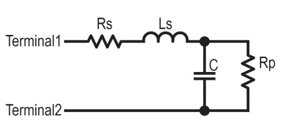
The simple capacitor equivalent circuit taught in school

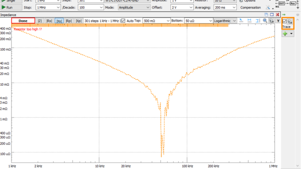
Inductors are more like a resistor in series with an ideal inductor, resistors can be inductors as well, and well, capacitors aren’t just simply a capacitance in a package. Little with electronics is as plain and simple in reality as basic theory would have you believe. [Tahmid Mahbub] was measuring an electrolytic capacitor with an LCR and noticed it measuring 19 uF despite the device being rated at 470 uF. This was because such parts are usually specified at low frequencies, and at a mere 100 kHz, it was measuring way out of the specification they were expecting. [Tahmid] goes into a fair bit of detail regarding how to model the equivalent circuit of a typical electrolytic capacitor and how to determine with a bit more accuracy what to expect.

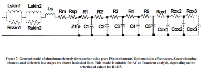
An aluminium electrolytic capacitor is more like this

The basic equivalent circuit for a capacitor has a series resistance and inductance, which covers the connecting leads and any internal tabs on the plates. A large-valued parallel resistor models the leakage through the dielectric in series with the ideal capacitance, which is responsible for the capacitor’s self-discharge property. However, this model is still too simple for some use cases. A more interesting model, shown to the left, comprises a ladder of distributed capacitances and associated resistances that result in a progressively longer time-constant component as you move from C1 to C5. This resembles more closely the linear structure of the capacitor, with its rolled-up construction. This model is hard to use in any practical sense due to the need to determine values for the components from a physical part. Still, it is useful to understand why such capacitors perform far worse than you would expect from just a simple equivalent model that looks at the connecting leads and little else.

Continue reading “Why Is My 470uF Electrolytic Cap More Like 20uF?”

Building A Spot Welder From 500 Junk Capacitors

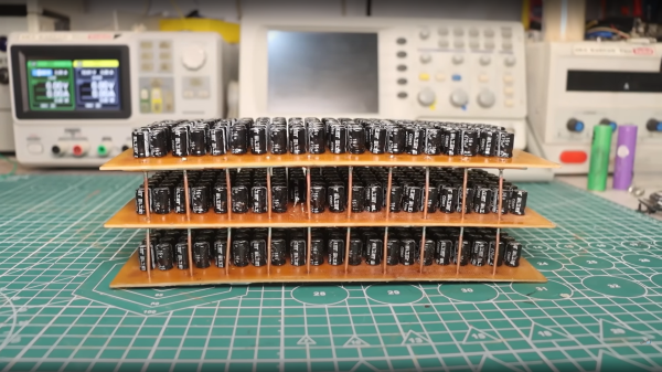
[Kasyan TV] over on YouTube was given a pile of spare parts in reasonably large quantities, some of which were useful and allocated to specific projects, but given the given the kind of electronics they’re interested in, they couldn’t find a use for a bag of 500 or so low specification 470uF capacitors. These were not low ESR types, nor high capacitance, so unsuitable for power supply use individually. But, what about stacking them all in parallel? (video, embedded below) After a few quick calculations [Kasyan] determined that the total capacitance of all 500 should be around 0.23 Farads with an ESR of around 0.4 to 0.5 mΩ at 16V and packing a theoretical energy total of about 30 joules. That is enough to pack a punch in the right situation.

A PCB was constructed to wire 168 of the little cans in parallel, with hefty wide traces, reinforced with multiple strands of 1.8mm diameter copper wire and a big thick layer of solder over the top. Three such PCBs were wired in parallel with the same copper wire, in order to keep the total resistance as low as possible. Such a thing has a few practical uses, since the super low measured ESR of 0.6mΩ and large capacitance makes it ideal for smoothing power supplies in many applications, but could it be used to make a spot welder? Well, yes and no. When combined with one of the those cheap Chinese ‘spot welder’ controllers, it does indeed produce some welds on a LiPo cell with a thin nickel plated battery strip, but blows straight through it with little penetration. [Kasyan] found that the capacitor bank could be used in parallel with a decent LiPo cell giving a potentially ideal combination — a huge initial punch from the capacitors to blow through the strip and get the weld started and the LiPo following through with a lower (but still huge) current for a little longer to assist with the penetration into the battery terminal, finishing off the weld.

[Kaysan] goes into some measurements of the peak current delivery and the profile thereof, showing that even a pile of pretty mundane parts can, with a little care, be turned into something useful. How does such an assembly compare with a single supercapacitor? We talked about supercaps and LiPo batteries a little while ago, which was an interesting discussion, and in case you’re still interested, graphene-based hybrid supercapacitors are a thing too!

Continue reading “Building A Spot Welder From 500 Junk Capacitors”

Chasing Down Bad Caps To Save A Troubled PSU

We know what you’re thinking. It’s a bad power supply, of course it was capacitors to blame. But even if we all intuitively know at this point that bad caps are almost always the culprit when a PSU gives up the ghost, it’s not always easy to figure out which one is to blame. Which is why this deep dive into a failed ETK450AWT by [eigma] is worth a look.

The first sign of trouble was when the computer would unexpectedly reboot with nothing in the system logs to indicate a problem. Eventually, [eigma] noticed a restart before the operating system even loaded, which confirmed the hardware was to blame. A quick look at the PSU output with a voltmeter showed things weren’t too far out of spec, but putting an oscilloscope on the 12 V line uncovered a nasty waveform that demanded further investigation.

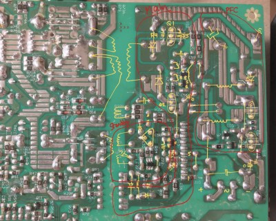
Connecting all the dots.

By carefully following traces and comparing with common PSU diagrams, [eigma] was able to identify the SG5616 IC that checks the various voltages being produced by the PSU and generates the PWR_OK signal which tells the motherboard that everything is working normally. As before, all of the DC voltages at this chip seemed reasonable enough, but the pin that was measuring AC voltage from the transformer was showing the same ripple visible on the 12 VDC line.

Even more digging uncovered that the transformer itself had a control IC nestled away. The 13 VDC required by this chip to operate is pulled off the standby transformer by way of a Zener diode and a couple capacitors, but as [eigma] soon found, the circuit was producing another nasty ripple. Throwing a few new capacitors into the mix smoothed things out and got the PSU to kick on, but that’s not quite the end of the story.

Pulling the capacitors from the board and checking their values with the meter, [eigma] found they too appeared to be within reasonable enough limits. They even looked in good shape physically. But with the help of a signal generator, he was able to determine their equivalent series resistance (ESR) was way too high. Case closed.

While swapping out blown capacitors in older electronics is something of a rite of passage for hardware hackers, this case is an excellent example of how even the simplest of fixes can be tricky to troubleshoot.

Hackaday Links Column Banner

Hackaday Links: March 15, 2020

Just a few weeks ago in the Links article, we ran a story about Tanner Electronics, the Dallas-area surplus store that was a mainstay of the hacker and maker scene in the area. At the time, Tanner’s owners were actively looking for a new, downsized space to move into, and they were optimistic that they’d be able to find something. But it appears not to be, as we got word this week from James Tanner that the store would be shutting its doors after 40 years in business. We’re sad to see anyone who’s supported the hardware hacking scene be unable to make a go of it, especially after four decades of service. But as we pointed out in “The Death of Surplus”, the center of gravity of electronics manufacturing has shifted dramatically in that time, and that’s changed the surplus market forever. We wish the Tanner’s the best of luck, and ask those in the area to stop by and perhaps help them sell off some of their inventory before they close the doors on May 31.

Feel like getting your inner Gollum on video but don’t know where to begin? Open source motion capture might be the place to start, and Chordata will soon be here to help. We saw Chordata as an entry in the 2018 Hackaday Prize; they’ve come a long way since then and are just about to open up their Kickstarter. Check out the video for an overview of what Chordata can do.

Another big name in the open-source movement has been forced out of the organization he co-founded. Eric S. Raymond, author of The Cathedral and the Bazaar and co-founder and former president of the Open Source Initiative has been removed from mailing lists and banned from communicating with the group. Raymond, known simply as ESR, reports that this was in response to “being too rhetorically forceful” in his dissent from proposed changes to OSD, the core documents that OSI uses to determine if software is truly open source. Nobody seems to be saying much about the behavior that started the fracas.

COVID-19, the respiratory disease caused by the newly emerged SARS-CoV-2 virus, has been spreading across the globe, causing panic and claiming lives. It’s not without its second-order effects either, of course, as everything from global supply chains to conferences and meetings have been disrupted. And now, coronavirus can be blamed for delaying the ESA/Russian joint ExoMars mission. The mission is to include a Russian-built surface platform for meteorological and biochemical surveys, plus the ESA’s Rosalind Franklin rover. Program scientists are no longer able to travel and meet with their counterparts to sort out issues, severely crimping productivity and forcing the delay. Social distancing and working from home can only take you so far, especially when you’re trying to get to Mars. We wonder if NASA’s Perseverance will suffer a similar fate.

Speaking of social distancing, if you’ve already decided to lock the doors and hunker down to wait out COVID-19, you’ll need something to keep you from going stir crazy. One suggestion: learn a new skill, like PCB design. TeachMePCB is offering a free rigid PCB design course starting March 28. If you’re a newbie, or even if you’ve had some ad hoc design experience, this could be a great way to productively while away some time. And if that doesn’t work for you, check out Bartosz Ciechanowski’s Gears page. It’s an interactive lesson on why gears look like they do, and the math behind power transmission. Ever wonder why gear teeth have an involute shape? Bartosz will fix you up.

Stay safe out there, everyone. And wash those hands!

Getting A Handle On ESR With A Couple Of DIY Meters

Got a bunch of questionable electrolytic caps sitting in your junk bin? Looking to recap a vintage radio chassis? Then you might need to measure the equivalent series resistance of the capacitors, in which case this simple five-transistor ESR meter might come in handy.

Even if you have no need for an ESR meter, [W2AEW]’s video below is a solid introduction to how ESR is determined. The circuit itself comes from EEVBlog forum user [Jay-Diddy_B] and is about as simple as such a circuit can get. Two transistors form an oscillator that generates a square wave that drives a resistor bridge network. The two legs of the bridge feed matched common-emitter amps, one leg through the device under test. The difference in voltage between the two legs is read on a meter, and you have a quick and simple way to sort through the caps in your junk bin. [Jay-Diddy_B]’s circuit is only presented in breadboard form; no attempt was made to field a practical instrument. Indeed, [W2AEW] already built a home-brew ESR meter using hex inverters and op amps to which he compares the five-transistor circuit’s results. His intention here seems to be to clarify the technique of ESR measurement and evaluate an even simpler circuit than his. We think he’s done a good job on both counts.

We’ve featured plenty of [WA2AEW]’s work before, like this Michigan Mity-Mite transmitter or his primer on oscilloscopes. We really like his laid back style and the way he makes complex topics easy to understand. Check them out.

Continue reading “Getting A Handle On ESR With A Couple Of DIY Meters”