Making a GPS clock is a relatively straightforward process on the face of it. Buy a GPS module for a few dollars, hook it up to a microcontroller board of your choice, pick the appropriate library and write a bit of code, et voila! A clock with time-wonk bragging rights!
Of course, your GPS clock will always tell the right time, but it won’t be really right. Your microcontroller will introduce all sorts of timing errors and jitter, so at best it’ll only be nearly right. [Rick MacDonald] has been striving to quantify and minimise these errors in his OpenPPS project, which aims to be as accurate a GPS time and frequency reference as possible.
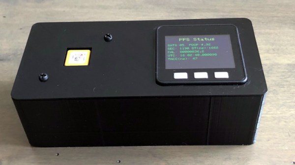
In a very comprehensive multi-page write-up, he details his progression, through the GPS modules he used, his experience with timing jitter when he used an ESP32 alone to process their output, and then his experiments with an FPGA and then temperature-compensated oscillators. It moves from being a mere description of a GPS clock into a fascinating run-down of both GPS timing itself and the development pitfalls he encountered along the way. At the end of it all he has a GPS clock in a smart 3D-printed enclosure which he admits as yet doesn’t do anything more than tell the time, but as he points out it’s a clock with minimised jitter, delay, and drift, and it remains an ongoing project that will evolve into a full-blown time and frequency standard.
If your taste in GPS clocks is far more simple, there are plenty of projects showing how a more basic one can be produced.