[Will Dana] is engineering his way to better sleep hygiene. Not satisfied with a simple bedtime reminder notification — such things are easily dismissed, after all — [Will] is offloading self-control onto a robot which will take his phone away at bedtime.
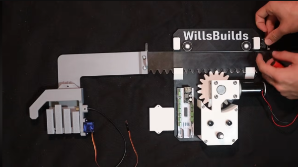
Scrolling in bed is allowed up to a prescribed time. At that time, a rack and pinion-mounted arm rises up from behind his mattress, presenting an open hand, ready to accept the object of his addiction. At this point, a countdown begins. If he does not hand over the device in a matter of seconds, the robot escalates by flashing obnoxiously bright lights in his face.
The nocturnal technology detox is not absolute, however. A button allows [Will] to temporarily retrieve his phone after it has been confiscated. This safety override accounts for the Inevitable situation where he will need to send a last-minute text before nodding off. The flashing light disincentive countdown is restarted upon retrieval, ensuring that [Will] does not cheat his own system for additional scroll time.
As a brief sidebar, [Will] does a nice job explaining how pulse-width modulation works for the purpose of controlling the speed of the rack and pinion mechanism.
For more of [Will’s] projects see this iPad suspension system a Lamp that tracks the location of the ISS and a drum that uses the piezoelectric effect to charge mobile devices.
Continue reading “This Bedtime Bot Enforces Better Sleep Hygiene”


 durability and increase noise. On the other hand, helical gears have a more gradual engagement, resulting in reduced noise and smoother operation. This leads to an increased load-carrying capacity, thus improving durability and lifespan.


