We’ll beat everyone to the punch: yes, actually building a working Turing machine, especially one that uses a Raspberry Pi, is probably something that would have pushed [Alan Turing]’s buttons, and not in a good way. The Turing machine is, above all else, a thought experiment, an abstraction of how a mechanical computing machine could work. Building a working one seems to be missing the point.
Thankfully, [Michael Gardi] has ignored that message three times now, and with good reason: some people just grok abstract concepts better when they can lay their hands on something and manipulate it. His TMD-1 was based on 3D printed tiles with embedded magnets — arranging the tiles on a matrix containing Hall effect sensors programmed the finite state machine, with the “tape” concept represented by a strip of eight servo-controlled flip cards. While TMD-1 worked fine, it had some limitations, which [Mike] quickly remedied with TMD-2, a decidedly more complicated affair that used a Raspberry Pi, a camera, and OpenCV to read an expanded state machine with six symbols and six states, without breaking the budget on all the Hall sensors required.
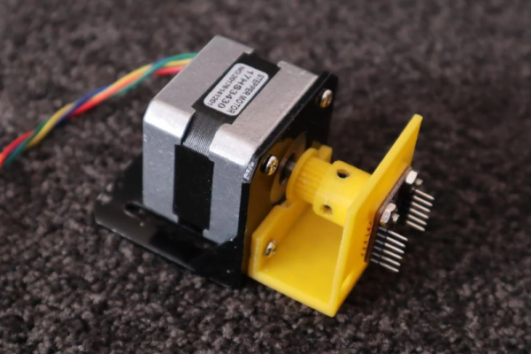
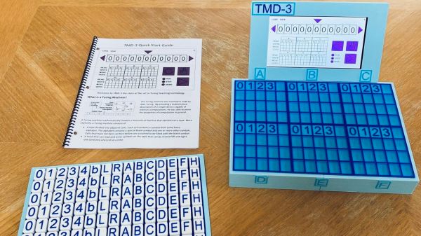
TMD-3 refines the previous design, eschewing the machine vision approach and returning to the Hall effect roots of the original. But instead of using three sensors per tile, [Mike] determined that one sensor would suffice as long as he could mount the magnet at different depths within each tile. That way, the magnetic field for each symbol could be discerned by a single Hall sensor, greatly reducing complexity and expense. An LCD screen and a Raspberry Pi run a console app that shows the tape status, the state machine, and the state transitions.
[Mike] put a ton of work into this one — there are nineteen project logs — and he includes a lot of useful tips and tricks, like designing PCBs directly in KiCAD before even having a schematic. Of course, with a track record like his, we’d expect nothing less.
Continue reading “TMD-3: Clever Hall Sensor Hack Leads To Better Turing Demo”