Pivots for e-textiles can seem like a trivial problem. After all, wires and fabrics bend and flex just fine. However, things that are worn on a body can have trickier needs. Snap connectors are the usual way to get both an electrical connection and a pivot point, but they provide only a single conductor. When [KOBAKANT] had a need for a pivoting connection with three electrical conductors, they came up with a design that did exactly that by using a flexible circuit board integrated to a single button snap.
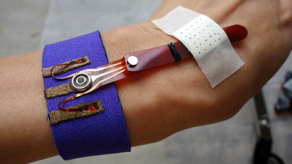
This interesting design is part of a solution to a specific requirement, which is to accurately measure hand movements. The photo shows two strips connected together, which pivot as one. The metal disk near the center is a magnet, and underneath it is a Hall effect sensor. When the wrist bends, the magnet is moved nearer or further from the sensor and the unit flexes and pivots smoothly in response. The brief videos embedded below make it clear how the whole thing works.
Continue reading “Three-Conductor Pivot For E-Textiles Is Better Than Wires”