[Pete] wondered how real-time clock modules could be selling on eBay for $1.50 when the main component, the Maxim DS3231 RTC/TCXO chip, cost him more like $4 apiece. Could the cheap modules contain counterfeit chips?
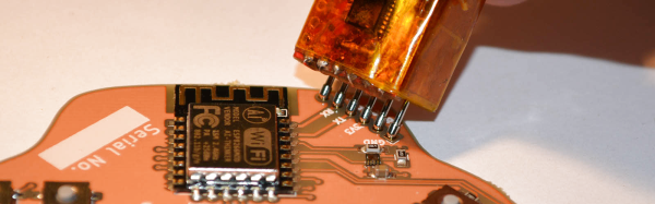
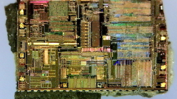
Well, sure they could. But in this case, they didn’t, and [Pete] has the die shots to prove it. He started off by clipping the SOIC leads rather than desoldering — he’s not going to be reusing this chip after he’s cut it in half. Next was a stage of embrittling the case by heating it up with a lighter and dunking it in water. Then he went at it with sandpaper.
It’s cool. You can see the watch crystal inside, and all of the circuitry. The DS3231 includes a TCXO — temperature-corrected crystal oscillator — and it seems to have a bank of capacitors that it connects and disconnects depending on the chip’s temperature to keep the oscillator running at the right speed. [Pete] used one in an offline situation, and it only lost sixteen seconds over a year, so we’d say that they work fine.
If you’d like to know more about how crystals are used to keep time, check out [Jenny]’s excellent article. And if sixteen second per year is way too much for you, tune up your rubidium standard and welcome to the world of the time nuts.