Trio Of Mods Makes Delta Printer More Responsive, Easier To Use

Just about any 3D printer can be satisfying to watch as it works, but delta-style printers are especially hypnotic. There’s just something about the way that three linear motions add up to all kinds of complex shapes; it’s mesmerizing. Deltas aren’t without their problems, though, which led [Bruno Schwander] to undertake a trio of interesting mods on his Anycubic Kossel.

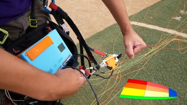
First up was an effort to reduce the mass of the business end of the printer, which can help positional accuracy and repeatability. This started with replacing the stock hot-end with a smaller, lighter MQ Mozzie, but that led to cooling problems that [Bruno] addressed with a ridiculously overpowered brushless hairdryer fan. The fan expects a 0 to 5-VDC signal for the BLDC controller, which meant he had to build an adapter to allow Marlin’s 12-volt PWM signal to control the fan.

Once the beast of a fan was tamed, [Bruno] came up with a clever remote mount for it. A 3D-printed shroud allowed him to mount the fan and adapter to the frame of the printer, with a flexible duct connecting it to the hot-end. The duct is made from lightweight nylon fabric with elastic material sewn into it to keep it from taut as the printhead moves around, looking a bit like an elephant’s trunk.

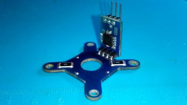
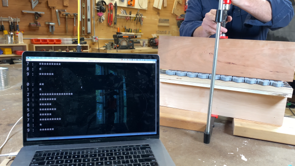
Finally, to solve his pet peeve of setting up and using the stock Z-probe, [Bruno] turned the entire print bed into a strain-gauge sensor. This took some doing, which the blog post details nicely, but it required building a composite spacer ring for the glass print bed to mount twelve strain gauges that are read by the venerable HX711 amplifier and an Arduino, which sends a signal to Marlin when the head touches the bed. The video below shows it and the remote fan in action.

Continue reading “Trio Of Mods Makes Delta Printer More Responsive, Easier To Use”

Exploring Woodworking Mysteries With Strain Gauges And Raspberry Pi

If you’re not a woodworker, you might not have heard of the “45-degree rule.” It goes like this: a clamp exerts a force that radiates out across a triangular region of the wood that forms a right angle — 45 degrees on each side of the clamp’s point of contact. So, to ensure that force is applied as evenly as possible across the entire glue joint, clamps should be spaced so that these force triangles overlap. It’s a handy rule, especially for the woodworker looking to justify the purchase of more clamps; you can never have too many clamps. But is it valid?

Myth busted?

The short answer that [ari kardasis] comes up with in the video below is… sort of. With the help of a wonderfully complex array of strain gauges and a Raspberry Pi, he found that the story isn’t so simple. Each strain gauge lives in a 3D printed bracket that spaces the sensors evenly along the wood under test, with a lot of work going into making the test setup as stiff as possible with steel reinforcement. There were some problems with a few strain gauges, but once he sorted that out, the test setup went into action.

[ari] tested clamping force transmission through pieces of wood of various widths, using both hardwoods and softwoods. In general, he found that the force pattern is much broader than the 45-degree rule suggests — he got over 60 degrees in some cases. Softwoods seemed to have a somewhat more acute pattern than hardwoods, but still greater than the rulebook says. At the end of the day, it seems like clamp spacing of two board widths will suffice for hardwoods, while 1.5 or so will do for softwoods. Either way, that means fewer clamps are needed.

A lot of woodworking is seat-of-the-pants stuff, so it’s nice to see a more rigorous analysis like this. It reminds us a lot of some of the experiments [Matthia Wandel] has done, like load testing various types of woods and glues.

Continue reading “Exploring Woodworking Mysteries With Strain Gauges And Raspberry Pi”

picture showing the re-built scale with an extra blue box with electronics on the bottom of it. on the scale, there's a transparent food-grade plastic glass with measurement marks on the side.

Urine Flow Measurement Made Accessible With UroFlow

If you’re dealing with a chronic illness, the ability to continuously monitor your symptoms is indispensable, helping you gain valuable insights into what makes your body tick – or, rather, mis-tick. However, for many illnesses, you need specialized equipment to monitor them, and it tends to be that you can only visit your doctor every so often. Thankfully, we hackers can figure out ways to monitor our conditions on our own. With a condition called BPH (Benign Prostate Hyperplasia), one of the ways to monitor it is taking measurements of urinary flow rate. Being able to take these measurements at home provides better insights, and, having found flow rate measurement devices to be prohibitively expensive to even rent, [Jerry Smith] set out to build his own.

This build is truly designed to be reproducible for anyone who needs such a device. Jerry has intricately documented the project and its inner workings – the 31-page document contains full build instructions, BOM for ordering, PCB description and pinout diagrams, calibration and validation instructions, and even software flowcharts; the GitHub repo has everything else you might need. We’re pleasantly surprised – this amount of documentation isn’t typically seen in hacker projects, and is even more valuable considering that this is a medical device that other hackers in need will want to reproduce.

Graph titled "Flow", with X axis saying "seconds" and Y axis saying "ml/Sec". There's differently colored plots on the graph, each apparently corresponding to a different measurement.
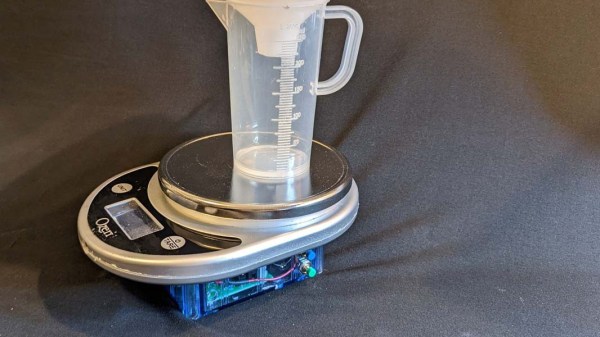
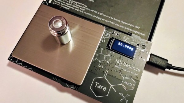
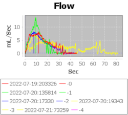
For the hardware, [Jerry] took a small digital scale of a certain model and reused its load cell-based weighing mechanism using an HX711 amplifier, replacing the screen and adding an extra box for control electronics. With an Arduino MKR1010 as brains of the operation, the hardware’s there to log flow data, initially recorded onto the SD card, with WiFi connectivity to transfer the data to a computer for plotting; a DS3234 RTC breakout helps keep track of the time, and a custom PCB ties all of these together. All of these things are easy to put together, in no small part due to the extensive instructions provided.

Continue reading “Urine Flow Measurement Made Accessible With UroFlow”

Finding The Right Hack Is Half The Battle

Sometimes you just get lucky. I had a project on my list for a long time, and it was one that I had been putting off for a few months now because I loathed one part of what it entailed — sensitive, high-accuracy analog measurement. And then, out of the blue I stumbled on exactly the right trick, and my problems vanished in thin air. Thanks, Internet of Hackers!

The project in question is a low-vacuum regulator for “bagging” fiberglass layups. What I needed was some way to read a pressure sensor and turn on and off a vacuum pump accordingly. The industry-standard vacuum gauges are neat devices, essentially a tiny little strain gauge on a membrane between the vacuum side and the atmosphere side, in a package the size of a dime. (That it’s a strain gauge is foreshadowing, but I didn’t know that at the time.) I bought one for $15 ages ago, and it sat on my desk, awaiting its analog circuitry.

See, the MPX2100 runs on 12 V and puts out a signal around 40 mV on top of a 6 V offset. That voltage level is inconvenient for modern 3.3 V microcontroller ADCs, and the resolution would get clobbered by the 6 V signal if I just put a voltage divider on it. This meant whipping together some kind of instrument amplifier circuit to null out the 6 V and amplify the 40 mV for the ADC. The circuits I found online all called for 1% resistors in values I didn’t have, and mildly special op-amps. No fun, for me at least. So there it sat.

Picture of sketchy-looking vacuum apparatus.
Cut the blue wire or the red wire? HX711 module and pressure sensor on the left.

Until I ran into this project that machetes through the analog jungle with one part, and it happened to be one I had on hand. A vacuum pressure sensor is a strain gauge, set up like a Wheatstone bridge, just like you would use for weighing something with a load cell. The solution? A load-cell ADC chip, the HX711, found in every cheap scale or online for under a buck. The only other trick was finding a low-voltage pressure sensor to work with it, but that turns out to be easy as well, and I had one delivered in two days.

In all, this project took months of foot-dragging, but only a few clicks and five minutes of soldering once I got the right idea. The industrial applications and manufacturers’ app notes all make sense if you are making hundreds or millions of these devices, where the one-time cost of prototyping up the hard bits gets amortized, but the hacker solution of using a weight-scale chip was just the ticket for a one-off. That just goes to show how useful sharing our tips and tricks can be — you won’t get this from the industry. So send us your success stories, and your useful failures too, and Read More Hackaday!

Custom Strain Gauges Help Keep Paraglider Aloft

No matter what they’re flying, good pilots have a “feel” for their aircraft. They know instantly when something is wrong, whether by hearing a strange sound or a feeling a telltale vibration. Developing this sixth sense is sometimes critical to the goal of keeping the number of takeoff equal to the number of landings.

The same thing goes for non-traditional aircraft, like paragliders, where the penalty for failure is just as high. Staying out of trouble aloft is the idea behind this paraglider line tension monitor designed by pilot [Andre Bandarra]. Paragliders, along with their powered cousins paramotors, look somewhat like parachutes but are actually best described as an inflatable wing. The wing maintains its shape by being pressurized by air coming through openings in the leading edge. If the pilot doesn’t maintain the correct angle of attack, the wing can depressurize and collapse, with sometimes dire results.

Luckily, most pilots eventually develop a feel for collapse, sensed through changes in the tension of the lines connecting the wing to his or her harness. [Andre]’s “Tensy” — with the obligatory “McTenseface” surname — that’s featured in the video below uses an array of strain gauges to watch to the telltale release of tension in the lines for the leading edge of the wing, sounding an audible alarm. As a bonus, Tensy captures line tension data from across the wing, which can be used to monitor the performance of both the aircraft and the pilot.

There are a lot of great design elements here, but for our money, we found the lightweight homebrew strain gauges to be the real gem of this design. This isn’t the first time [Andre] has flown onto these pages, either — his giant RC paraglider was a big hit back in January.

Continue reading “Custom Strain Gauges Help Keep Paraglider Aloft”

Cheap Lab Balance Needs Upgrades, Gets Gutted Instead

What is this world coming to when you spend seven bucks on a digital scale and you have to completely rebuild it to get the functionality you need? Is nothing sacred anymore?

Such were the straits [Jana Marie] found herself in with his AliExpress special, a portable digital scale that certainly looks like it’s capable of its basic task. Sadly, though, [Jana] was looking for a few more digits of resolution and a lot more in the way of hackability. And so literally almost every original component was ripped out of the scale, replaced by a custom PCB carrying an STM32 microcontroller and OLED display. The PCB has a complicated shape that allows the original lid to attach to it, as well as the stainless steel pan and load cell. [Jana] developed new firmware that fixes some annoying traits, for example powering down after 30 seconds, and adds new functionality, such as piece-counting by weight. The video below shows some of the new features in action.

Alas, [Jana] reports that even the original load cell must go, as it lacks the accuracy her application requires. So she’ll essentially end up building the scale from scratch, which we respect, of course. At this rate, she might even try to build her own load cell from SMD resistors too.

Continue reading “Cheap Lab Balance Needs Upgrades, Gets Gutted Instead”

Quartet Of SMD Resistors Used To Sense Z-Axis Height

Here’s a neat trick for your next 3D-printer build or retrofit: a Z-axis sensor using a DIY strain gauge made from SMD resistors. We’re betting it could have plenty of other applications, too.

Conventional load cells, at least the ones you can pick up cheaply from the usual sources or harvest from old kitchen or bathroom scales, are usually way too big to be used on the extruder of a 3D-printer. [IvDm] wanted to build a touch sensor for his Hybercube printer, so he built his own load cell to do it. It consists of four 1000 ohm SMD resistors in the big 2512 device size. He mounted them to an X-shaped PCB and wired them in the classic Wheatstone bridge configuration, with two resistors on one side of the board and two on the other.

The extruder mounts into a hole in the center of the board and floats on it. Through an HX711 load cell driver chip, the bridge senses the slight flex of the board when the extruder bottoms out on the bed, and an ATtiny85 pulls a limit switch input to ground. [IvDm] even did some repeatability testing with this sensor and it turned out to be surprisingly consistent. The first minute or so of the video below shows it in action on the Hypercube.

We found the use of SMD resistors as strain gauges pretty clever here, but there’s plenty to do with off-the-shelf load cells: measuring how much filament is left on a roll, checking the thrust of a model rocket engine, or even figuring out if you’re peeing correctly.

Continue reading “Quartet Of SMD Resistors Used To Sense Z-Axis Height”