I had one of those why-didn’t-I-think-of-it moments this week, reading this article about multiplexing I2C on the ESP32 microcontroller. The idea is so good, and so simple, that it’s almost silly that it’s not standard hacker practice. And above all, it actually helps solve a problem that I’ve got. This is why I read Hackaday every day.
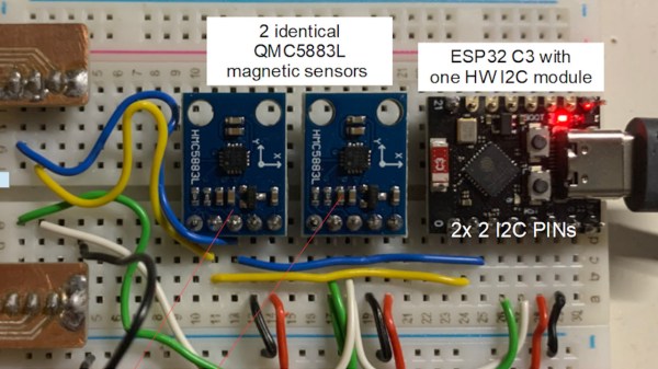
I2C is great in that it lets you connect up multiple devices to a pair of wires using a very bus architecture. Every device has its own address, the host calls them out, and hopefully all other devices keep quiet while just the right one responds. But what happens when you want to use a few of the same sensors, where each IC has the same address? The usual solution is to buy a multiplexer chip.
But many modern microcontrollers, like the ESP32, have an internal multiplexer setup that lets you map the pins with the dedicated hardware peripherals, usually at initialization time. Indeed, I’ve been doing it as an “init” task so long, I never thought to do it otherwise. But that’s exactly the idea behind [BastelBaus]’s hack – if you dynamically reassign the pins, you can do the I2C multiplexing with the chip you’ve got. This should probably work for any other chips that have multiple assignable pins for hardware peripherals as well.
Cool idea, but really simple. Why hadn’t I ever thought of it? I think it’s because I’ve always had this init / mainloop schema in my mind, which for instance the Arduino inherited and formalized in its setup() and loop() functions. Pin mappings go in the init section, right?
So what this hack really amounts to, for me, is a rethinking of what’s static and what’s dynamic. It’s always worth questioning your assumptions, especially when you’re facing a problem that requires a creative solution. Sometimes limitations are only in your mind. Have you had your mind opened recently by a tiny little hack?