This Four-Axis Stencil Printer Is The Ultimate In SMD Alignment Tools

Here at Hackaday we love all kinds of builds, and we celebrate anytime anyone puts parts together into something else. And while we love the quick and dirty builds, there’s just something about the fit and finish of this four-axis SMD stencil printer that really pushes our buttons.

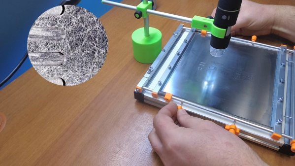
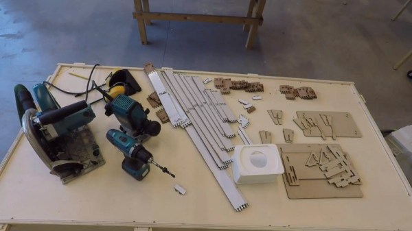
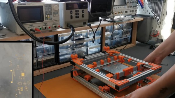
This build comes to us from [Phillip], who like many surface-mount users was sick of the various tape-and-PCB methods that are commonly used to align the solder stencil with the PCB traces. His solution is this fully adjustable stencil holder made from aluminum extrusions joined by 3D-printed parts. The flip-up frame of the device has a pair of clamps for securely holding the stainless steel stencil. Springs on the clamp guide rods provide some preload to keep the stencil taut as well as protection from overtensioning.

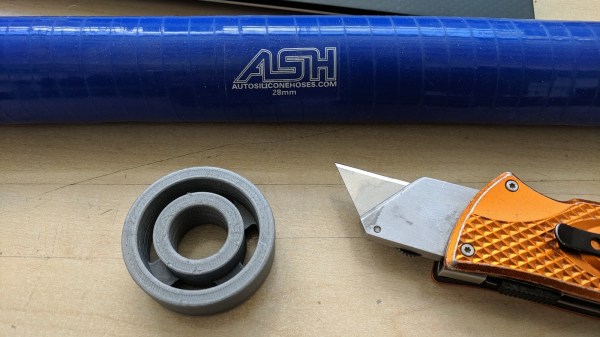
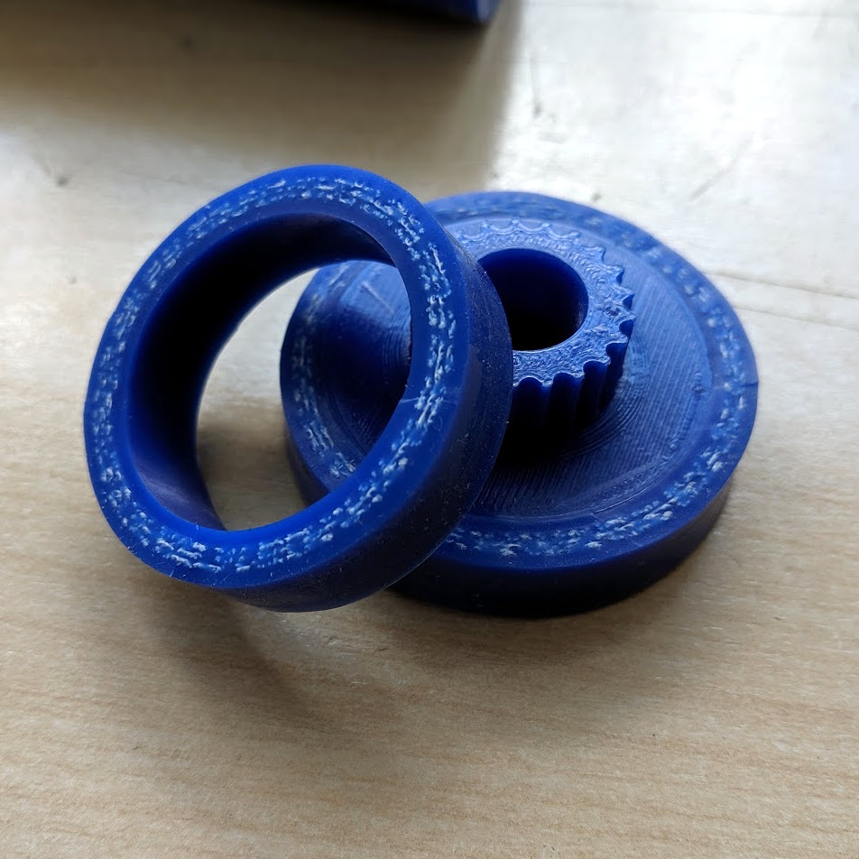
The stencil can move in the X-, Y-, and Z-axes to line up with a PCB held with 3D-printed standoffs on a bed below the top frame. The bed itself rotates slightly to overcome any skew in alignment of the PCB. [Phillip] was aghast at the price of an off-the-shelf slew-ring bearing for that axis, but luckily was able to print up some parts and just use simple roller bearing to do the same thing for a fraction of the cost. The frame is shown in use below; the moment when the pads line up perfectly through the stencil holds is oddly satisfying.

This puts us in mind of a recent, similar stencil printer we covered. That one was far simpler, but either one of these beats the expedient alignment methods hands down.

Continue reading “This Four-Axis Stencil Printer Is The Ultimate In SMD Alignment Tools”

Adjustable Jig Eases PCB Stencil Alignment Process

PCB stencils make application of solder paste a snap, but there’s a long, fussy way to go before the paste goes on. You’ve got to come up with some way to accurately align the stencil over the board, which more often than not involves a jury-rigged setup using tape and old PCBs, along with a fair amount of finesse and a dollop of luck.

Luckily, [Valera Perinski] has come up with a better way to deal with stencils. The Stencil Printer is a flexible, adjustable alignment jig that reduces the amount of tedious adjustment needed to get things just so. The jig is built mostly from aluminum extrusions and 3D-printed parts, along with a bunch of off-the-shelf hardware. The mechanism has a hinged frame that holds the stencil in a fixed position above a platen, upon which rests the target PCB. The board is held in place by clamps that ride on threaded rods; with the stencil flipped down over the board, the user can finely adjust the relative positions of the board and the stencil, resulting in perfect alignment. The video below is mainly a construction montage, but if you skip to about the 29:00 mark, you’ll see the jig put through its paces.

Granted, such a tool is a lot more work than tape and spare PCBs, but if you do a lot of SMD work, it may be worth the effort. It’s certainly less effort than a solder-paste dispensing robot.

Continue reading “Adjustable Jig Eases PCB Stencil Alignment Process”

Building One Test Fixture To Rule Them All

Test and programming fixtures are great time-savers for anyone who needs to deal with more than a handful of PCBs. Instead of plugging in connectors (or awkwardly holding probe tips or wires) to program some firmware or run tests, one simply pops a PCB into a custom fixture with one hand, and sips a margarita with the other while a program decides whether everything is as it should be. Test fixtures tend to be custom-made for specific board layouts, meaning one tester is needed per board or device type, but this work is easily justified by the huge time savings they offer.

An inserted PCB sits atop the thick acrylic piece, with pogo pins making contact from below. Generous space on the left and right make sure there is clearance for any mounted components. Visible near the bottom of the green board are output LEDs, and two touch-sensitive pads.

But the fine folks at Sparkfun’s quality control department figured they could save even more time by exploiting common design features across different boards, and shared details about designing a single test fixture flexible enough to handle multiple board types and designs.

The test unit looks like pretty familiar stuff at first glance: some hardware responsible for running the test program, laser-cut acrylic jig to hold a test PCB in a consistent position, spring-loaded pogo pins to make temporary electrical connections, and LEDs to clearly indicate PASS and FAIL states. The clever part is the way the fixture is designed to accommodate multiple board designs, and how it uses several 74LVC4066 quad bilateral switch ICs to take care of switching which pogo pins are connected and to where.

As mentioned, to be compatible with multiple boards there must be common design elements to exploit. In Sparkfun’s case, the through-hole connections on their breakout boards are all in a row with standard 0.1″ spacing. By using the aforementioned pogo pins and 4066 ICs, different pinouts can be accommodated and multiple board types can be used without any need to swap to different test hardware.

Test and programming fixtures, being one-offs, tend to have a lot of space for creativity and often show clever design or re-purposing of parts. Our own [Bob Baddeley] explains all about them here.

Super Easy Small Robot Wheels

Anyone who has delved into DIY wheels knows that they are a trickier than it may seem, especially if the wheels aren’t just for show and need to provide things like decent traction and durability. 3D printers have helped a lot, but they’re not a cure-all.

Check out how [Robert K.] makes wheels from segments of automotive silicone hose, which are constructed with fibers embedded within them for durability and structure. Not only are these hoses easily sourced, but the silicone makes a great wheel surface and the hoses themselves are highly durable. He uses a 3D printed jig to cut a slice of hose that press-fits perfectly onto a 3D printed hub. [Robert] finds that a 28 mm hose pulled over a 35 mm diameter wheel is a perfect fit.

These wheels are for a Beetleweight class combat robot, which are limited to three pounds (1.36 kg) or less. You can see some video of [Robert]’s previous Beetleweight robot named ‘Bourbon’, and we have featured what goes into the even-smaller Antweight class (one pound or less) in the past.

JigFab Makes Woodworking Easier

Woodworking is an age-old craft that requires creativity and skill to get the best results. Experienced hands get the best results, while the new builder may struggle to confidently produce even basic pieces. JigFab is here to level the playing field somewhat.

Much of the skill in woodworking comes with mastering the various joints and techniques required to hold a piece together. Cutting these joints often requires specialized tools and equipment – ideally, some sort of jig. These jigs can be difficult to build in themselves, and that’s where JigFab shines.

The workflow is straightforward and quite modern. A piece is designed in Autodesk Fusion 360. Various joints can then be defined in the model between individual parts. JigFab then generates a series of laser cut constraints that can be used with power tools to easily and accurately cut the necessary parts to build the final piece.

It’s an impressive technology which could rapidly speed the workflow of anyone experimenting with woodwork and design. There’s even smart choices, like having a toolkit of standard predefined elements that reduce laser cutting time when producing new constraints. If you’re eager to get stuck in to woodwork, but don’t know where to start, don’t worry – we’ve got a primer for that. Video after the break.

Continue reading “JigFab Makes Woodworking Easier”

Custom Jig Makes Short Work Of Product Testing

When you build one-off projects for yourself, if it doesn’t work right the first time, it’s a nuisance. You go back to the bench, rework it, and move on with life. The equation changes considerably when you’re building things to sell to someone. Once you take money for your thing, you have to support it, and anything that goes out the door busted is money out of your pocket.

[Brian Lough] ran into this fact of life recently when the widget he sells on Tindie became popular enough that he landed an order for 100 units. Not willing to cut corners on testing but also not interested in spending days on the task, he built this automated test jig to handle the job for him. The widget in question is the “Power BLough-R”, a USB pass-through device that strips the 5-volt from the line while letting the data come through; it’s useful for preventing 3D-printers from being backfed when connected to Octoprint. The tester is very much a tactical build, with a Nano in a breakout board wired to a couple of USB connectors. When the widget is connected to the tester, a complete series of checks make sure that there are no wiring errors, and the results are logged to the serial console. [Brian] now has complete confidence that each unit works before going out the door, and what’s more, the tester shaved almost a minute off each manual test. Check in out in action in the video below.

We’ve featured quite a few of [Brian]’s projects before. You may remember his Tetris-themed YouTube subscriber counter, or his seven-segment shoelace display.

Continue reading “Custom Jig Makes Short Work Of Product Testing”

Drill Jig Helps Mount WeMos D1 Mini

As far as ESP8266 boards go, the WeMos D1 Mini is a great choice if you’re looking to get started with hackerdom’s microcontroller du jour. It’s small, well supported, and can be had ridiculously cheap. Often going for as little as $3 USD each, we buy the things in bulk just to have spares on hand. But that’s not to say it’s a perfect board. For one, it lacks the customary mounting holes which would allow you to better integrate it into finished products.

This minor annoyance was enough to spring [Martin Raynsford] into action. He noticed there was some open area on the D1 Mini’s PCB where it seemed he could drill through to add his own mount points, but of course popping holes in a modern PCB can be risky business. There’s not a lot of wiggle room between success and heartbreak, and it’s not like the diminutive D1 Mini is that easy to hold down to begin with. So he designed a laser-cut jig to allow him to rapidly add mounting holes to his D1 Mini’s assembly line style.

For those who might be skeptical, [Martin] reports he’s seen no adverse effects from drilling through the board, though does admit it’s possible the close proximity of the metal screw heads to the ESP8266’s antenna may have a detrimental effect. That said, he’s tested them in his projects out to 25 m (82 feet) with no obvious problems. He’s using a 2 mm drill bit to make his hole, and M2 x 6 mm machine screws to hold the boards down.

The jig design is released as a SVG and DXF for anyone with a laser cutter to replicate, but it shouldn’t be too difficult to extrude those designs in the Z dimension for hackers who haven’t yet jumped on the subtractive manufacturing bandwagon.

When a project makes the leap from prototype to in-house production, designing and building jigs become an essential skill. From flashing firmware to doing final checkout, the time and effort spent building a jig early on will pay for itself quickly in production.