You see a lot of pneumatic actuators in industrial automation, and for good reason. They’re simple, powerful, reliable, and above all, cheap. Online sources and fluid-power suppliers carry a bewildering range of actuators, so why would anyone bother to make their own pneumatic cylinders? Because while the commercial stuff is cheap, it’s not PVC and plywood cheap.
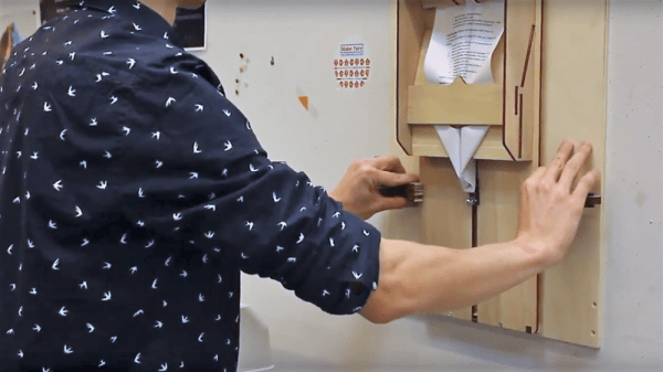
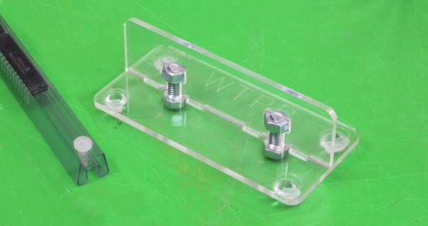
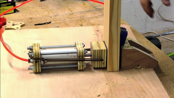
Granted, that’s not the only reason [Izzy Swan] gives for his DIY single-acting cylinder. For him it’s more about having the flexibility to make exactly what he needs in terms of size and shape. And given how ridiculously easy these cylinders are, you can make a ton of them for pennies. The cylinder itself is common Schedule 40 PVC pipe with plywood endcaps, all held together with threaded rod. [Izzy] cut the endcaps with a CNC router, but a band saw or jig saw would do as well. The piston is a plywood plug mounted to a long bolt; [Izzy] gambled a little by cutting the groove for the O-ring with a table saw, but no fingers were lost. The cylinder uses a cheap bungee as a return spring, but an internal compression spring would work too,. Adding a second air inlet to make the cylinder double-acting would be possible as well. The video below shows the cylinder in action as a jig clamp.
True, the valves are the most expensive part of a pneumatic system, but if nothing else, being able to say you made your own cylinders is a win. And maybe you’ll get the fluid-power bug and want to work up to DIY hydraulics.
Continue reading “Shop-Made Pneumatic Cylinders From PVC And Plywood”