Upgraded Raster Laser Projector Goes RGB

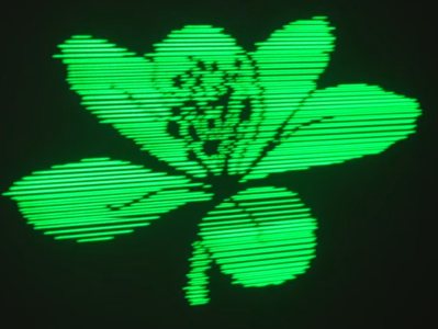
We’ve covered a scanning laser project by Ben Make’s Everything last year, and now he’s back with a significant update. [Ben]’s latest project now offers a higher resolution and RGB lasers. A couple of previous versions of the device used the same concept of a rotating segmented mirror synchronised to a pulsed laser diode to create scanlines. When projected onto a suitable surface, the distorted, pixelated characters looked quite funky, but there was clearly room for improvement.

More scanlines and a faster horizontal pixel rate

The previous device used slightly inclined mirrors to deflect the beam into scanlines, with one mirror per scanline limiting the vertical resolution. To improve resolution, the mirrors were replaced with identically aligned mirrors of the type used in laser printers for horizontal scanning. An off-the-shelf laser galvo was used for vertical scanning, allowing faster scanning due to its small deflection angle. This setup is quicker than then usual vector galvo application, as the smaller movements require less time to complete. Once the resolution improvement was in hand, the controller upgrade to a Teensy 4 gave more processing bandwidth than the previous Arduino and a consequent massive improvement in image clarity.

Finally, monochrome displays don’t look anywhere near as good as an RGB setup. [Ben] utilised a dedicated RGB laser setup since he had trouble sourcing the appropriate dichroic mirrors to match available lasers. This used four lasers (with two red ones) and the correct dichroic mirrors to combine each laser source into a single beam path, which was then sent to the galvo. [Ben] tried to find a DAC solution fast enough to drive the lasers for a proper colour-mixing input but ended up shelving that idea for now and sticking with direct on-off control. This resulted in a palette of just seven colours, but that’s still a lot better than monochrome.

The project’s execution is excellent, and care was taken to make it operate outdoors with a battery. Even with appropriate safety measures, you don’t really want to play with high-intensity lasers around the house!

Here’s the previous version we covered, a neat DIY laser galvo using steppers, and a much older but very cool RGB vector projector.

Continue reading “Upgraded Raster Laser Projector Goes RGB”

Archiving Data On Paper Using 2D Images

It seems like only yesterday we covered a project using QR codes to archive data on paper (OK, it was last Thursday), so here’s another way to do it, this time with a dedicated codec using the full page. Optar or OPTical ARchiver is a project capable of squeezing a whopping 200 Kb of data onto a single A4 sheet of paper, with writing and reading achieved with a standard laser printer and a scanner. It’s a bit harder than you might think to get that much data on the page, given that even a 600 DPI printer can’t reliably place every dot each time. Additionally, paper is rarely uniform at the microscopic scale, so Optar utilizes a forward error-correcting coding scheme to cater for a little irregularity in both printing and scanning.

The error-correcting scheme selected was an Extended Golay code (24, 12, 8),  which, interestingly, was also used for image transmission by the NASA Voyager 1 and 2 missions. In information theory terms, this scheme has a minimum Hamming Distance of 8, giving detection of up to seven bit errors. This Golay code implementation is capable of correcting three-bit errors in each 24-bit block, with 12 bits available for payload. That’s what the numbers in those brackets mean.

Another interesting problem is paper stretch during printing. A laser printer works by feeding the paper around rollers, some of which are heated. As a printer wears or gets dirty, the friction coefficient along the rollers can vary, leading to twisting and stretching of the paper during the printing process. Water absorbed by the paper can also lead to distortion. To compensate for these effects, Optar regularly inserts calibration targets throughout the bit image, which are used to locally resynchronize the decoding process as the image is processed. This is roughly similar to how the alignment patterns work within larger QR codes. Finally, similar to the position detection targets (those square bits) in QR codes, Optar uses a two-pixel-wide border around the bit image. The border is used to align to the corners well enough to locate the rows of bits to be decoded.

In the distant past of last week, we covered a similar project that uses QR codes. This got us thinking about how QR codes work, and even if encoding capacity can be increased using more colors than just black and white?

Thanks to [Petr] for the tip!

Retrotechtacular: The $175,000 Laser Printer

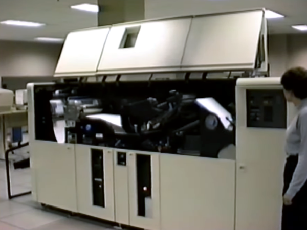
Laser printers today are cheap and readily available. But in 1976, they were the height of printing technology. The IBM 3800 was the $175,000 printer to have in that year. (Video, embedded below.) But you couldn’t have one on your desktop. Even if you could afford it, the thing is the size of a car, and we don’t even want to guess what it weighs. The printer took tractor-fed continuous form paper and could do 167 pages a minute at about 150 dots per inch (actually 180 x 144). For the record, that was as much as 1.7 miles of paper an hour!

In those days, people who would use this printer traditionally had massive banks of noisy impact printers. We imagine this device saved many data processing person’s hearing. Compared to a modern laser printer, though, it needed a lot of maintenance. For example, the initial models needed a xenon flash lamp replaced every month, although later models could go years on one bulb. Looking at some of the hardware in the video, it was probably made closer to the end of life for these printers which were made through 1999.

Continue reading “Retrotechtacular: The $175,000 Laser Printer”

£D printed parts with glossy toner transfer images on

Add Full-Color Images To Your 3D Prints With Toner Transfer

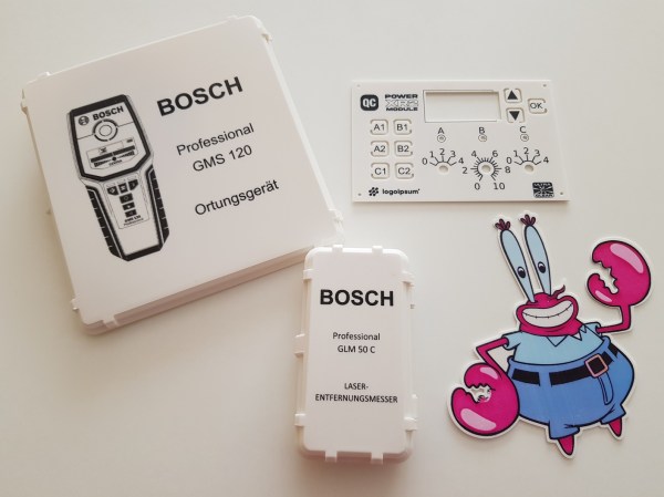
Toner transfer is a commonly-used technique for applying text and images to flat surfaces such as PCBs, but anybody who has considered using the same method on 3D prints will have realized that the heat from the iron would be a problem. [Coverton] has a solution that literally turns the concept on its head, by 3D printing directly onto the transparency sheet.

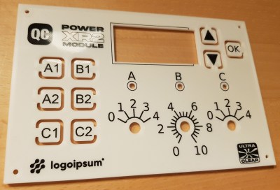
instrument panel design with toner transfer markings
The fine detail is great for intuitive front-panel designs

The method is remarkably straightforward, and could represent a game-changer for hobbyists trying to achieve professional-looking full-color images on their prints.

First, the mirrored image is printed onto a piece of transparency film with a laser printer. Then, once the 3D printer has laid down the first layer of the object, you align the transparency over it and tape it down so it doesn’t move around. The plastic that’s been deposited already is then removed, and a little water is placed on the center of the bed. Using a paper towel, the transparency gets smoothed out until the bubbles are pushed off to the edges.

Another few pieces of tape hold the transparency down on all corners, and the hotend height is adjusted to take into account the transparency thickness. From there, the print can continue on as normal. When finished, the image should be fused with the plastic. If it’s hard to visualize, check out the video after the break for a step-by-step guide.

There are, of course, some caveats. Aligning the transfer and the print looks a little fiddly at the moment, the transparency material used (obviously) has to be rated for use in laser printers, and it only works on flat surfaces. But on the other hand, there will be some readers who already have everything they need to try this out at home right now — and we’d love to see the results!

We’ve covered some other ways to get color and images onto 3D prints in the past, such as this hydrographic technique or by using an inkjet printhead, but [Coverton]’s idea looks much simpler than either of those.  If you’re interested in toner transfer for less heat-sensitive materials, then check out this guide from a few years back, or see what other Hackaday readers have been doing on wood or brass.

Continue reading “Add Full-Color Images To Your 3D Prints With Toner Transfer”

S400 Scanner Modified For Finding Hidden Watermarks

Computer hardware is by and large compromised out of the box. Whether it’s sloppy factory code, or government-installed backdoors, it’s difficult to trust anything. A great example is that of color laser printers, the vast majority of which place hidden watermarks on printed pages. It’s a somewhat forgotten issue these days, but back in 2005, [bunnie] set out to modify a scanner to help better image and investigate these watermarks.

The watermarks in question have been investigated by the EFF, and often, but not always, consist of tiny yellow dots printed on the page. They can store data such as the name of the computer that printed the document, as well as the serial number and model of the printer used. With this functionality baked into the firmware, all prints made on such a printer are compromised.

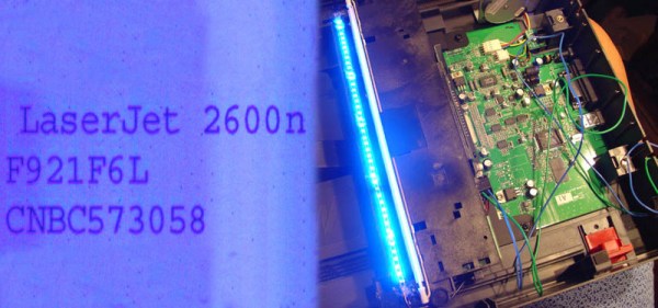
The easiest way to see these watermarks is with blue light, which is reflected by the white paper, but causes yellow dots to show up as dark spots. To make scanning affected documents quick and easy, [bunnie] whipped up a linear LED light array, installing it in a spare slot in his scanner’s light assembly, next to the stock white CCFL. Usage is a little more complex, with the scanner’s automatic calibration getting confused if the blue LEDs are left on at the start of a scan. Instead, the LEDs must be turned off initially, and then powered up once the calibration is complete.

Results are good, with the tiny dots made much clearer in the test scans [bunnie] performed. Unfortunately, the watermarking technology has moved on, and it’s likely that modern printers use a variety of techniques that are even harder to detect. By and large, ransom notes are best made the old fashioned way – by cutting up some old magazines.

The 3D Printer Packing Problem

Form Labs recently announced the launch of the Fuse 1, a desktop SLS printer that will print all your parts using nylon powder and a laser. This a fundamentally different method of 3D printing as compared to filament-based machines, and the best way to use a Fuse 1 is to fill the entire volume of the machine with 3D printed parts. [Michael Fogelman] decided to investigate the 3D packing problem, and managed to fill this printer with the maximum number of 3D printed tugboats. If you’re wondering, it’s 113, as compared with 82 tiny Benchies using naive bin packing.

The formal definition of this sort of problem is the bin packing problem, or simply calculating the maximum number of items can be packed into a finite volume. There is no general solution to this problem, and it’s probably impossible to create an algorithm that will solve this problem for any collection of 3D models. Nevertheless, it’s possible to create a solution that shows marked improvement over a naive solution.

[Michael]’s solution involves simulated annealing. This algorithm begins by randomly placing tugboats, then mutating the position or rotation of one of the boats for each iteration. The code is less than 1000 lines of Go and is available on GitHub if you already have an SLS printer at your disposal.

It should be noted this type of problem isn’t particularly new to the world of 3D printers. There have been a few tools to solve the bin-packing problem for filament-based printers, but the solutions to these problems are two-dimensional; since filling a bed is a problem that only uses the ‘shadow’ of the Z-axis of each part, it’s a slightly easier problem to solve.

Now that Form Labs’ Fuse 1 SLS printer has been announced, there is a new application for this type of problem in the space of 3D printers. It’s not a perfect solution — and it’s doubtful there will ever be a perfect solution — but if you’re looking for a way to fill the volume of your powder printer with parts, this is the best you’re going to do.

Want To Make A PCB? The Pantum Knows…

We’ve done a lot of PCBs with the toner transfer method over the years. The idea is simple: print a pattern using toner (which is just ground up black plastic) and then use an iron or other heat and pressure device to transfer the toner to a copper-clad board. It works and it works well. But getting just the right combination of heat, pressure, release paper, and toner is sometimes tricky.

Some people hack their printers to turn off the fuser wire (to make the toner not stick to the paper) or to run a PCB directly through it. If you have a big expensive laser printer, though, you might not want to chop it up just to run PCBs. Have you looked at laser printer prices lately? We aren’t sure if it is cheap units flooding the market, or the overwhelming popularity of color printers, but you can pick up a Pantum P2500 for about $25 or $30–and probably get WiFi printing at that price. [Mlermen] picked one of these up and shows you how to convert it to a PCB printer.

Continue reading “Want To Make A PCB? The Pantum Knows…”