As you probably know, we love our clocks here at Hackaday. Odd display technologies are always interesting to see, as are unusual encoding techniques such as binary, ternary or higher-radix number systems. Still, clocks are typically meant to be human-readable, even if their encoding might be a little eccentric.
[Kitchi] however built an LED-based clock that is not human-readable, at least not without quite a bit of training. This is because it displays the time by generating a QR code, which only becomes readable to most humans through the use of a smartphone app. Of course, this negates the need for a clock since your smartphone will already have one anyway — but whoever said a clock needs to be useful?
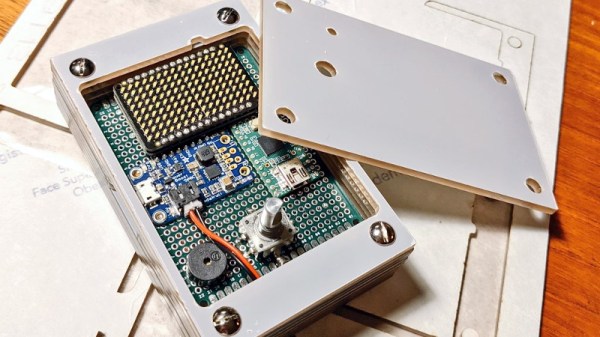
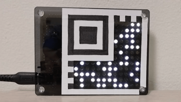
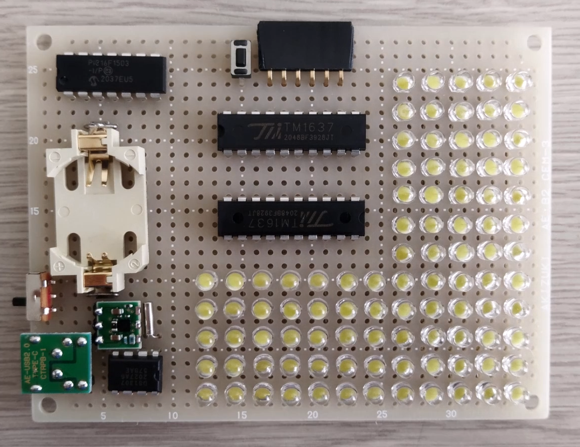 To be fair, the display could conceivably be read by a determined human, since the QR format used is the tiny Micro QR M2 version that measures only 13×13 pixels. It’s capable of storing ten decimal digits, just enough to hold the date and time in mmddhhmmss format. The fixed part of the QR code is made of paper, while the variable part is formed through a grid of 90 white LEDs. The LEDs are mounted on a piece of prototype board along with a PIC 16F1504 microcontroller, two TM1637 LED drivers and a DS1307 real-time clock with battery backup.
If decoding QR codes is not your thing, or you simply haven’t got your smartphone on you, then the QR clock can also be set to a more human-readable format by adding a jumper. The time will then scroll across the LED screen in ordinary decimal format.
The video in the link is in Japanese, with no automatic translation available, but the build process is clearly shown and should be understandable even if you can’t follow the cheerful robotic narrator. We’ve seen a couple of QR-code based clocks before, some with an LCD screen and some with retro styling, but all of those use the larger standard QR code which definitely no human can decode visually. Or can you? Let us know in the comments!
Thanks for the tip, [J. Peterson]!