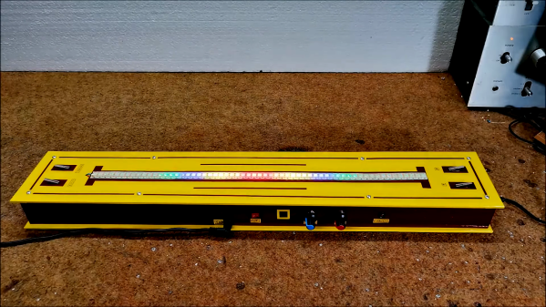
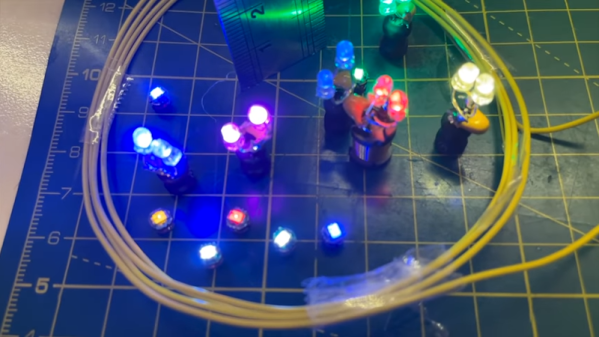
Flashing LEDs are all well and good, but they’re even better if they can sync up with ambient sounds or music. [mircemk] has built the LUMAZOID visualizer to do just that, relying on some staple maker components to do so.
The build is open-source, and designed to work with strings of 60, 120, or 180 WS2812B LEDs. An Arduino Nano is charged with running the show, capturing audio via its analog-to-digital converter. A sensitivity pot enables the input level to be set appropriately.
From there, a Fast Fourier Transform is taken, providing data on the intensity of the audio in various frequency bins. The LUMAZOID can be set up to respond to just bass or to all frequencies as a whole. This data is then used to pulse the LEDs in time with the beat.
It’s a fun project that demonstrates the basic techniques required to build an audio-reactive visualizer. We’ve seen some other great builds in this space before, too. Video after the break.
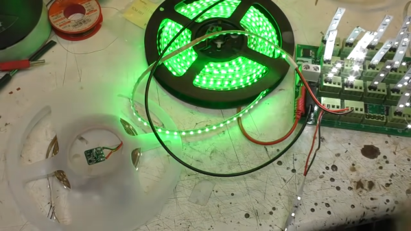
While addressable LED strips are all the rage, [Mike] from [mikeselectricstuff] has been working on an installation using the more basic two-wire strips that are simply controlled via PWM dimming. He’s recently figured out a tidy way to send sensor signals down these strips without adding any additional cabling.
The circuit in question.
The build uses 24 V LED tape, which consists of gangs of 6 LEDs in series with a forward voltage of 3V. Thus, these strips don’t even begin to light until approximately 18V is across them.
By adding a 15 V Zener diode and a resistor across the MOSFET which dims the LEDs, a voltage of around 9 V can be put across the LEDs without lighting them up when the MOSFET PWM dimmer is in its off phase. A PIC10F322 microcontroller and an accelerometer can then be run from this voltage, with the aid of a 3.3 V regulator wired in parallel with the LEDs. The regulator must also be able to handle the full 24 V when the LEDs are switched on.
A transistor is also wired up, switching a 2.2 K resistor in parallel with the LEDs. When turned on by the PIC, this transistor causes roughly a 10 mA current to flow through the Zener diode and its series resistor. The voltage developed across that series resistor can be measured as the transistor is turned on and off. In this case, the pulse width used to turn that transistor on is relative to motion detected by the accelerometer on the end of the LED strip.
Turning the LEDs on at 100% duty cycle prevents the system working, as the pulse widths generated by the sensor circuit can’t be detected when the LED line is held high all the time. However, in practice, it matters not — running the LEDs at a maximum 98% duty cycle eliminates the issue.
It’s an ingenious way to send sensor signals down a two-wire LED strip, even if it does take a second to wrap one’s head around it. It also seems to do a great job of adding motion-reactive effects to the LED strips in question. It’s not the first LED project we’ve seen from [Mike], either. Video after the break.
[Atomic14] bought some wireless LEDs that receive power from a base station. They were very neatly packaged, but — we like it — he took one apart and made his own versions. They may not look as polished, but they work and they are undeniably cool.
The LEDs work by receiving power from an induction coil. Once you have power, lighting up an LED is no big deal. Reverse engineering found the transmitter sends 217 kHz into a 2.2 mH inductor. A capacitor resonates the coil and drives the attached LED.
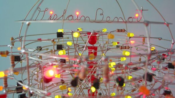
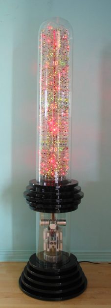
Here at Hackaday, we pride ourselves on bringing you the very freshest of hacks. But that doesn’t mean we catch all the good stuff the first time around, and occasionally we get a tip on an older project that really should have been covered the first time around. This remarkable circuit sculpture clock is a perfect example of one that almost got away.
[Gislain Benoit] creation is called “The Tower” for good reason: it’s built inside what amounts to a giant glass test tube. Inverted and adorned with MDF discs, the Pyrex tube stands 5 feet (1.5 meters) tall, and is absolutely stuffed with electronic goodness. There are more than 2,100 discrete components mounted inside on a helical framework of carefully bent wires, forming a vertical sculpture that displays the time on three separate pairs of seven-segment displays. All the diode-transitor logic circuits are built from discrete components; nary a chip was used, and to spice things up, [Gislain] used LEDs in place of regular diodes everywhere in the circuit. The result is a constant light show as the clock goes through its paces.
The whole thing looks amazing, and even the power supply at the base works in the overall presentation. The design is a bit of a departure from [Gislain]’s previous circuit sculpture clock, but it’s just as beautiful, and equally as mind-boggling in terms of construction difficulty.
Thanks to [Maarten] for the belated tip on this one.
If you’re a flashlight person, you know that there’s little you would do to get the brightest, most powerful, most ridiculous flashlight possible. You might even decide to build yourself a ludicrously powerful flashlight, like [Maciej Nowak] did.
If you choose the DIY route, be warned that it’s probably not going to be a simple process, at least if you follow [Maciej]’s lead. His flashlight is machined out of aluminum rounds, all turned down on the lathe to form the head of the flashlight. The head is made from three parts, each of which acts as a heat sink for the five 20-Watt CREE XHP70 LED modules. The LEDs are mounted with care to thermal considerations, and wired in series to DC-DC converter that provides the necessary 30 V using a battery pack made from four 21700 Li-ion cells. The electronics, which also includes a BMS for charging the battery and a MOSFET switching module, form a tidy package that fits into the aluminum handle.
The video below shows that the flashlight is remarkably bright, with a nice, even field with no hotspots. Given the 45-minute useful life and the three-hour recharge time, it might have been nice to make it so anywhere from one to five of the LEDs could be turned on at once. Some interesting effects might be had from switching the LEDs on sequentially, too.
Given the proclivities of our community, it’s no surprise that this is hardly the first powerful flashlight we’ve seen. This one broke the 100-Watt barrier with a single COB LED, while this ammo-can version sports an even higher light output. Neither of them looks much like a traditional flashlight, though, which is where [Maciej]’s build has the edge.
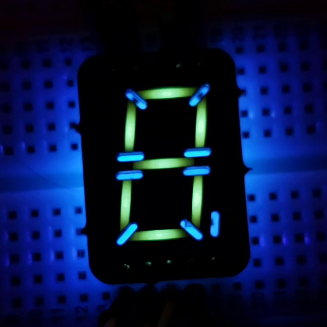
It’s interesting what you see when you train a black light on everyday objects. We strongly suggest not doing this in a hotel room, but if you shine UV light on, say, a printed circuit board, you might see what [Sam Ettinger] did, which led him to build these cool low-profile seven-segment fluorescent PCB displays.
As it turns out, at least some FR-4 PCBs fluoresce under UV light, giving off a ghostly blue-green glow. Seeing the possibilities, [Sam] designed a PCB with cutouts in the copper and solder mask in the shape of a traditional seven-segment display. The backside of the PCB has pads for UV LEDs and current-limiting resistors, which shine through the board and induce the segments to glow. Through-slots between the segments keep light from one segment from bleeding over into the next; while [Sam] left the slots unfilled, they could easily be filled with solder. The fluorescent property of FR-4, and therefore the brightness and tint of the segments, seems to vary by board thickness and PCB manufacturer, but it looks like most PCBs will show pretty good results.
We’d say the obvious first improvement might be to cover the back of the display with black epoxy, to keep stray light down, and to improve contrast. But they look pretty great just as they are. We can also see how displays with other shapes, like icons and simple symbols. Or maybe even alphanumeric characters — say, haven’t we seen something like that before?
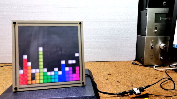
Fast Fourier Transforms. Spectrum Analyzers. Waterfall displays. Not long ago, such terms were reserved for high end test gear. But oh, how things have changed! It’s no surprise to many Hackaday readers that modern microcontrollers have transformed the scene as they become more powerful and as a result are endowed with more and more powerful software libraries. [mircemk] has used such a library along with other open source software combined with mostly off the shelf hardware to create what he calls the DIY FFT Spectrum Analyzer. Rather than being a piece of test gear, this artful project aims to please the eye.
The overall build is relatively simple. Audio is acquired via a line-in jack or a microphone, and then piped into an ESP32. The ESP32 runs the audio through the FFT routine, sampling, slicing, and dicing the audio into 16 individual bands. The visual output is displayed on a 16 x 16 WS2812 Led Matrix. [mircemk] wrote several routines for displaying the incoming audio, with a waterfall, a graph, and other visualizations that are quit aesthetically pleasing. Some of them are downright mesmerizing! You can see the results in the video below the break.
Of course the build doesn’t stop with slapping some hardware and a few passive components together. To really be finished, it needs to be encased in something worth displaying. [mircemk] does not disappoint, as a beautiful 3D-printed enclosure wraps it all up nicely.
We think that the final product is great, and it reminds us of some of the very things that inspired us early on in our hacking careers. We would love to see this project integrated with an Interactive Musical Art Installation of any kind, the more esoteric the better. Perhaps a 555 timer synth could fit the bill? Be sure to share your own hacks with us via the Tip Line!

 Here at Hackaday, we pride ourselves on bringing you the very freshest of hacks. But that doesn’t mean we catch all the good stuff the first time around, and occasionally we get a tip on an older project that really should have been covered the first time around.