We rarely take a moment to consider the beauty of the components we use in electronic designs. Too often they are simply commodities, bought in bulk on reels or in bags, stashed in a drawer until they’re needed, and then unceremoniously soldered to a board. Granted, little scraps of black plastic with silver leads don’t exactly deserve paeans sung to their great beauty – at least not until you cut them in half to reveal the beauty within.
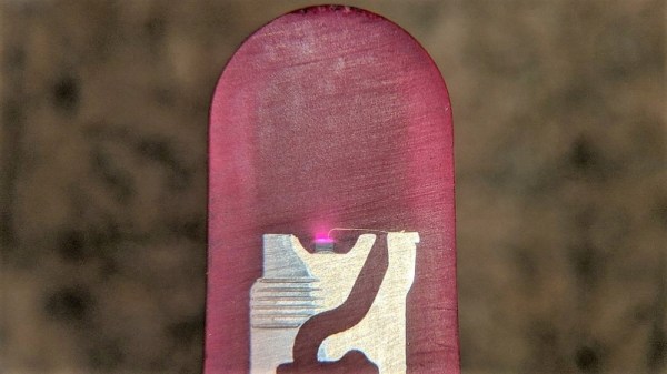
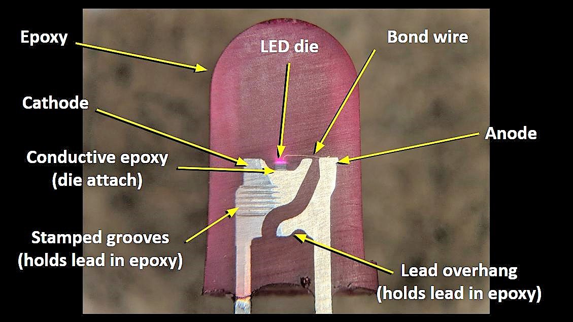 We’ve seen a little of what [Tube Time] has accomplished here; recall this lapped-down surface-mount inductor that [electronupdate] did a while back. The current work is more extensive and probably somewhat easier to accomplish because [TubeTime] focused mainly on larger through-hole components such as resistors and capacitors. It’s not clear how the sections were created, but it is clear that extreme care was taken to lap down the components with enough precision that the inner structures are clearly visible, and indeed, carefully enough that some, most notably the LED, still actually work. For our money, though, the best looking cross-sections are the capacitors, especially the electrolytic, for which [Tube Time] thoughtfully provides both radial and axial sections. The little inductor is pretty cool too. Some of the component diagrams are annotated, too, which makes for fascinating reading.
Honestly, we could look at stuff like this all day.
Thanks to [Stuart Rogers] for the tip.