There’s something seriously wrong with the Arduino walkie-talkie that [GreatScott!] built.
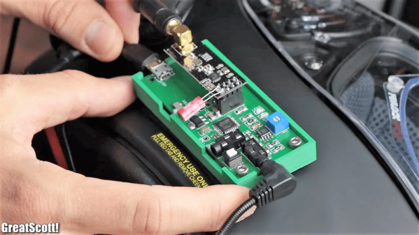
The idea is simple: build a wireless intercom so a group of motor scooter riders can talk in real-time. Yes, such products exist commercially, but that’s no fun at all. With a little ingenuity and a well-stocked parts bin, such a device should be easy to build on the cheap, right?
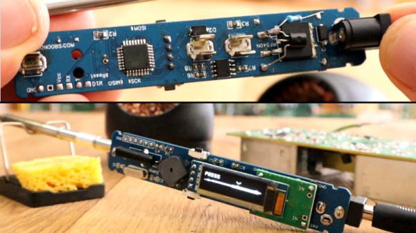
Apparently not. [GreatScott!] went with an Arduino-based design, partly due to familiarity with the microcontroller but also because it made the RF part of the project seemingly easier due to cheap and easily available nRF24 2.4 GHz audio streaming modules. Everything seems straightforward enough on the breadboard – an op-amp to boost the signal from the condenser mic, a somewhat low but presumably usable 16 kHz sampling rate for the ADC. The radio modules linked up, but the audio quality was heavily distorted.
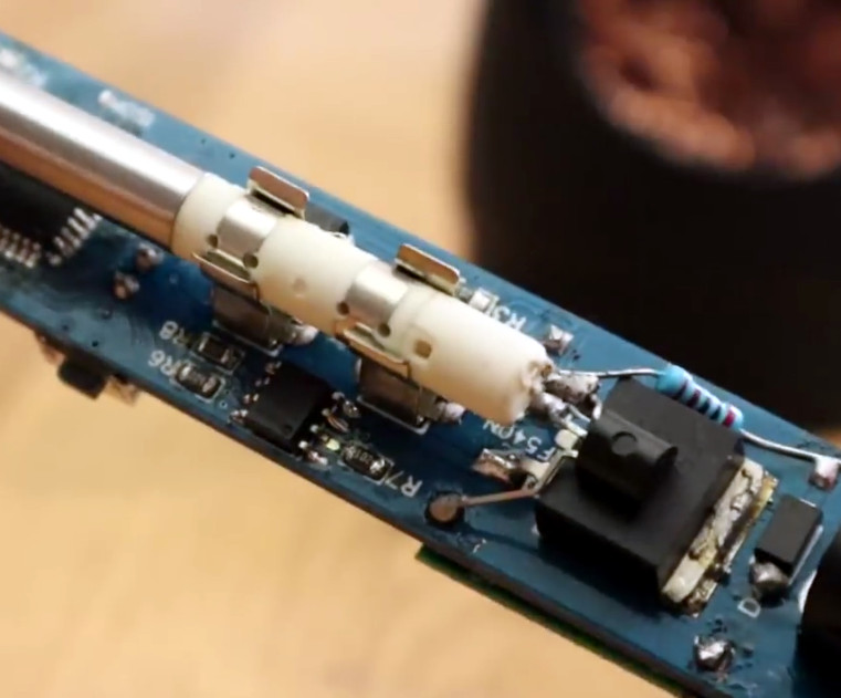
[GreatScott!] assumed that the rat’s nest of jumpers on the breadboard was to blame, so he jumped right to a PCB build. It’s a logical step, but it seems like it might be where he went wrong, because the PCB version was even worse. We’d perhaps have isolated the issue with the breadboard circuit first; did the distortion come from the audio stage? Or perhaps did the digitization inject some distortion? Or could the distortion be coming from the RF stage? We’d want to answer a few questions like that before jumping to a final design.
We love that [GreatScott!] has no issue with posting his failures – we’ve covered his suboptimal CPU handwarmer, and his 3D-printed BLDC motor stator was a flop too. It’s always nice to post mortem these things to avoid a similar fate.
Continue reading “Fail Of The Week: The Arduino Walkie That Won’t Talkie”