Reverse Engineering An Insulin Pump With An SDR And Decapping

Insulin pumps are a medical device used by people with diabetes to automatically deliver a measured dose of insulin into their bloodstream. Traditionally they have involved a canula and separate connected pump, but more recent models have taken the form of a patch with a pump mounted directly upon it. When [Pete Schwamb]’s daughter received  one of these pumps, an Omnipod, he responded to a bounty offer for reverse engineering its RF protocol. As one of the people who helped create Loop, an app framework for controlling insulin delivery systems, he was in a particularly good position to do the work.

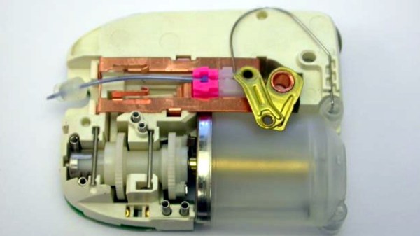
The reverse engineering itself started with the familiar tale of using an SDR to eavesdrop on the device’s 433MHz communication between pump and control device. Interrogating the raw data was straightforward enough, but making sense of it was not. There was a problem with the CRC algorithm used by the device which had a bug involving a bitwise shift in the wrong direction, then they hit a brick wall in the encryption of the data. Hardware investigation revealed a custom chip in the device, and there they might have stalled.

But the international reverse engineering community is not without resources and expertise, and through the incredible work of a university researcher in the UK (whose paper incidentally includes a pump teardown) they were able with an arduous process supported by many people to have the firmware recovered through decapping the chip. Even once they had thus extracted the encryption code and produced their own software their problems were not over, because communication issues necessitated a much better antenna on the RileyLink Bluetooth bridge boards that translated Bluetooth from a mobile phone to 433 MHz for the device.

This precis doesn’t fully encapsulate the immense amount of work over several years by a large group of people with some very specialist skills that reverse engineering the Omnipod represents. To succeed in this task is an incredible feat, and makes for a fascinating write-up.

Thanks [Alex] for the tip.

High-Style Ball Balancing Platform

If IKEA made ball-balancing PID robots, they’d probably look like this one.

This [Johan Link] build isn’t just about style. A look under the hood reveals not the standard, off-the-shelf microcontroller development board you might expect. Instead, [Johan] designed and built his own board with an ATmega32 to run the three servos that control the platform. The entire apparatus is made from a dozen or so 3D-printed parts that interlock to form the base, the platform, and the housing for the USB webcam that’s perched on an aluminum tube. From that vantage point, the camera’s images are analyzed with OpenCV and the center of the ball is located. A PID loop controls the three servos to center the ball on the platform, or razzle-dazzle it a little by moving the ball in a controlled circle. It’s quite a build, and the video below shows it in action.

We’ve seen a few balancing platforms before, but few with such style. This Stewart platform comes close, and this juggling platform gets extra points for closing the control loop with audio feedback. And for juggling, of course.

Continue reading “High-Style Ball Balancing Platform”

[Jeri] Builds A Magnetic Loop Antenna

Most new hams quickly learn that the high-frequency bands are where the action is, and getting on the air somewhere between 40- and 160-meters is the way to make those coveted globe-hopping contacts. Trouble is, the easiest antennas to build — horizontal center-fed dipoles — start to claim a lot of real estate at these wavelengths.

So hacker of note and dedicated amateur radio operator [Jeri Ellsworth (AI6TK)] has started a video series devoted to building a magnetic loop antenna for the 160- and 80-meter bands. The first video, included after the break, is an overview of the rationale behind a magnetic loop. It’s not just the length of the dipole that makes them difficult to deploy for these bands; as [Jeri] explains, propagation has a lot to do with dipole height too. [Jeri] covers most of the mechanical aspects of the antenna in the first installment; consuming a 50-foot coil of 3/4″ copper tubing means it won’t be a cheap build, but we’re really looking forward to seeing how it turns out.

We were sorry to hear that castAR, the augmented reality company that [Jeri] co-founded, shut its doors back in June. But if that means we get more great projects like this and guided tours of cool museums to boot, maybe [Jeri]’s loss is our gain?

Continue reading “[Jeri] Builds A Magnetic Loop Antenna”

Looptaggr: Endless Graffiti

If your problem is how to put out a maximum amount of repetitive graffiti with a minimum amount of effort, we’ve got your solution. Or rather, [Ariel Schlesinger] and [Aram Bartholl] had your solution way back in 2010. The banner image says it all.

Of course, it doesn’t have to be graffiti that you’re spraying. This idea could be easily adapted to stencil that repeating floral pattern that my grandmother had on her walls too. It’s like a patterned paint roller, but for a spray can.

There’s room for improvements here. For instance, we can’t cut out stencils to save our life but we know where to find a laser cutter. From the look of things, they could use a slightly bigger stencil and something to catch the drips. There’s probably an optimal size for this gizmo, which calls for experimentation.

We’re somewhat obsessed with graffiti machines. Whether it’s a graffiti quadcopter or the elegant and non-permanent sidewalk-chalker style bots, we like machines that make “art”. What’s your favorite graffiti hack?

Thanks [n0p;n0p;n0p;] for the (archival) tip!

Hackaday Prize Entry: Industrial Servo Control On The Cheap

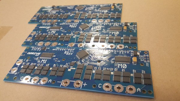
[Oscar] wonders why hobby projects ignore all the powerful brushless motors available for far less than the equivalent stepper motors, especially with advanced techniques available to overcome their deficiencies.  He decided it must be because there is simply not a good, cheap, open source motor controller out there to drive them precisely. So, he made one.

Stepper motors are good for what they do, open-loop positioning along a grid, but as far as industrial motors go they’re really not the best technology available. Steppers win on the cost curve for being uncomplicated to manufacture and easy to control, but when it comes to higher-end automation it’s servo control all the way. The motors are more powerful and the closed-loop control can be more precise, but they require more control logic. [Oscar]’s board is designed to fill in this gap and take full advantage of this motor control technology.

The board can do some pretty impressive things for something with a price goal under $50 US dollars. It supports two motors at 24 volts with up to 150 amps peak current. It can take an encoder input for full closed loop control. It supports battery regeneration for braking. You can even augment a more modest power supply to allow for the occasional 1 KW peak movement with  the addition of a lithium battery. You can see the board showing off some of its features in the video after the break.

Continue reading “Hackaday Prize Entry: Industrial Servo Control On The Cheap”

Stomp Box Synthesizer

[Brian McNamara] fed the output of his guitar pedal back into its input creating a looped synthesizer. He started with an effects pedal he made but now we think he’s ended up with an electronic stomp box. Check out the results in the video after the break. Now he needs to make the knobs foot-friendly so he can monkey with this while playing guitar.

Continue reading “Stomp Box Synthesizer”

Looping Foot Pedal

This guitar pedal can record, playback, and modify samples. [Colin Merkel], also know for his work on electronic door locks, built this to replicate some guitar effects he heard in recordings. By tapping the button at the bottom with your foot the device begins recording. Another tap stops the recording and starts the loop. That’s where the rest of the controls take over, with settings to adjust the speed of playback, volume, and the type of playback looping. The video after the break gives a great demonstration of these features.

[Colin] built this around a PIC 18F877A with a 256k RAM chip to store the sample. There’s a bunch of other components that go into this and we’re dumbfounded that he built it on protoboard. This would be a multi-breadboard prototype for us and we wouldn’t think twice about laying out and etching our own PCB. He admits that the point-to-point soldering stretched his skills to the limit but he doesn’t say how many hours it took to get the circuit up and running. This is a great addition to the cool guitar pedals we’ve seen here.

Continue reading “Looping Foot Pedal”