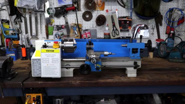
A 1/5th scale hydraulic jack model

Miniature Hydraulic Jack Is A Scale Marvel

Most hydraulic jacks are big tools that can lift upwards of 1000 kg but [Maker B]’s is quite a bit smaller than average.

The world’s smallest hydraulic jack is a tiny hand-machined model made out of tiny pieces of iron, brass and copper. But here’s the kicker: It’s a real hydraulic jack with real hydraulic fluid! At 1/5th scale, it obviously isn’t as strong as a full-size jack, but it can still easily lift an impressive 24 soda cans! Switching between the lathe and mill, [Maker B] shows how all the parts of the jack are made from stock metal in detail, and even explains in simple terms how a hydraulic jack works in this masterpiece of a video.

Over the years, we’ve seen plenty of tiny objects cranked out from stock pieces of metal — often bolts. But the fact that the end result here is a working tool, puts it into a decidedly less common niche. Of course, given what we’ve seen from [Maker B] in the past, it’s hardly a surprise.
Continue reading “Miniature Hydraulic Jack Is A Scale Marvel”

Making An Injection Mold For Yourself

Injection molding is the obvious onward step from 3D printing when the making of a few plastic parts becomes their series manufacture. The problem with injection molding is though, that making a mold can be prohibitively expensive. Has the advent of affordable CNC machining changed that? [Teaching Tech] takes a look, and machines a mold for part of a bicycle bracket.

With a diversion into home-made silicone seals for the injection molding machine, he proceeds to machine the mold itself from a block of aluminium. It’s a basic introduction to mold construction for those of us who’ve never ventured in this direction before, and it provides some interesting lessons. As we’d expect he does a rough machining pass before returning with a ball-end tool to smooth off those curves, but there’s a lesson in measuring rather than believing the paperwork. The tool he used was a bit smaller then the spec, so his path left some rough edges that had to be returned to. Otherwise the use of a removable pair of bolts to form holes in the finished part is we guess obvious after watching the video, but it’s something we learned as injection molding newbies.

This video follows on from a previous one we also covered, in which we’re introduced to the machine itself.

Continue reading “Making An Injection Mold For Yourself”

Hackaday Prize 2023: Machining Metals With Sparks

Working with metals can present a lot of unique challenges even for those with a fairly well-equipped shop. Metals like aluminum and some types of steel can be cut readily with grinders and saws, but for thick materials or some hardened steels, or when more complex cuts need to be made, mechanical cutting needs to be reconsidered in favor of something electric like electrical discharge machining (EDM) or a plasma cutter. [Norbert] has been on the path of building his own EDM machine and walks us through the process of generating a spark and its effects on some test materials.

Armed with a microscope, a homemade high-voltage generator, drill bit, and a razor blade to act as the workpiece, [Norbert] begins by experimenting with electrical discharges by bringing the energized drill bit close to the razor to determine the distance needed for effective electrical machining. Eventually the voltage is turned up a bit to dive into the effects of higher voltage discharges on the workpiece. He also develops a flushing system using de-ionized water, and then finally a system to automate the discharges and the movement of the tool.

While not a complete system yet, the videos [Norbert] has created so far show a thorough investigation of this metalworking method as well as some of the tricks for getting a setup like this working. EDM can be a challenging method for cutting metal as we’ve seen before with this similar machine which uses wire as the cutting tool, but some other builds we’ve seen with more robust electrodes have shown some more promise.

Continue reading “Hackaday Prize 2023: Machining Metals With Sparks”

Learning 3D Printing Best Practices From A Pro

It might seem like 3D printing is a thoroughly modern technology, but the fact is, it’s been used in the industry for decades. The only thing that’s really new is that the printers have become cheap and small enough for folks like us to buy one and plop it on our workbench. So why not take advantage of all that knowledge accumulated by those who’ve been working in the 3D printing field, more accurately referred to as additive manufacturing, since before MakerBot stopped making wooden printers?

That’s why we asked Eric Utley, an applications engineer with Protolabs, to stop by the Hack Chat this week. With over 15 years of experience in additive manufacturing, it’s fair to say he’s seen the technology go through some pretty big changes. Hes worked on everything from the classic stereolithography (SLA) to the newer Multi Jet Fusion (MJF) printers, with a recent focus on printing in metals such as Inconel and aluminum. Compared to the sort of 3D printers he’s worked with, we’re basically playing with hot, semi-melted, LEGOs — but that doesn’t mean some of the lessons he’s learned can’t be applied at the hobbyist level. Continue reading “Learning 3D Printing Best Practices From A Pro”

Machining A Golf Ball To Make A Lovely Tactile Volume Knob

Golf balls are wonderfully tactile things. They have a semi-grippy covering, and they’re a beautiful size and weight that sits nicely in the hand. Sadly, most of them just get smacked away with big metal clubs. [Jeremy Cook] recognized their value as a human interface device, though, and set about turning one into a useful volume knob.

The trick here is in the machining. [Jeremy] used a 3D printed jig to hold a golf ball tightly in place so that it could be machined using a milling machine. With the bottom taken off and a carefully-designed 3D printed insert in the bottom, the golf ball is ready to be used as a knob for a volume control. As for the hardware side of things, [Jeremy] used an existing USB keypad, fitting the golf ball onto the encoder for volume and seek control in various programs.

The results sadly weren’t ideal. While the golf ball sits nicely upon the encoder, [Jeremy] found the device uncomfortable to use. Size may be an issue, but we also suspect the crowding of the surrounding buttons has a role to play. It forces the wrist into an uncomfortable curve to access the ball without hitting the surrounding controls. Without that, it may be greatly improved.

Files are available for those wishing to make their own. We don’t get a lot of golf ball builds here on Hackaday, but we’d love to see more. Hit up the tipsline if you’ve got ’em. Video after the break.

Continue reading “Machining A Golf Ball To Make A Lovely Tactile Volume Knob”

Tactical Build Makes Machining Splined Shaft A Snap

Quick, what’s 360 divided by 23? It’s easy enough to get the answer, of course, but if you need to machine a feature every 15.652 degrees around a shaft, how exactly would you accomplish that? There are a number of ways, but they all involve some degree of machining wizardry. Or, you can just make the problem go away with a little automation.

The story behind [Tony Goacher]’s Rotary Table Buddy begins with some ATV tracks he got off AliExpress. His idea is to build a specialty electric vehicle for next year’s EMF Camp. The tracks require a splined shaft to drive them, which would need to be custom-made on a milling machine. A rotary table with a dividing plate — not as fancy as this one, of course –is usually the answer, but [Tony] was a little worried about getting everything set up correctly, so he embarked on a tactical automation solution to the problem.

An RP2040 provided the brains of the project, while a NEMA 23 stepper provides the brawn. [Tony] whipped up a quick PCB and 3D printed a case for the microcontroller, a stepper driver, an LCD display, and a few buttons. He 3D printed an adapter and a shaft coupler to mount the stepper motor to a rotary table. From there it was just a matter of coming up with a bit of code to run everything.

There’s a brief video in [Tony]’s blog post that shows Rotary Table Buddy in action, indexing to the next position after cutting one of the 23 splines. He says it took about ten minutes to cut each spline using this setup, which probably makes to total cutting time far less than the amount of time invested in the tool. But that’s hardly the point, and besides, now he’s set up for all kinds of machining operations in the future.

And we sure hope we hear about the EMF Camp build, too.

Stripped Clock Wheel Gets A New Set Of Teeth, The Hard Way

If there’s one thing we’ve learned from [Chris] at Clickspring, it’s that a clockmaker will stop at nothing to make a clock not only work perfectly, but look good doing it. That includes measures as extreme as this complete re-toothing of a wheel from a clock. Is re-toothing even a word?

The obsessive horologist in this case is [Tommy Jobson], who came across a clock that suffered a catastrophic injury: a sudden release of energy from the fusee, the cone-shaped pulley that adjusts for the uneven torque created by the clock’s mainspring. The mishap briefly turned the movement into a lathe that cut the tops off all the teeth on the main wheel.

Rather than fabricate a completely new wheel, [Tommy] chose to rework the damaged one. After building a special arbor to hold the wheel, he turned it down on the lathe, leaving just the crossings and a narrow rim. A replacement blank was fabricated from brass and soldered to the toothless wheel, turned to size, and given a new set of teeth using one of the oddest lathe setups we’ve ever seen. Once polished and primped, the repair is only barely visible.

Honestly, the repaired wheel looks brand new to us, and the process of getting it to that state was fascinating to watch. If the video below whets your appetite for clockmaking, have we got a treat for you.

Continue reading “Stripped Clock Wheel Gets A New Set Of Teeth, The Hard Way”