There are several reasons you should have an isolation transformer. They can prevent ground loops and also prevent a device under test from having a DC path to ground (or isolate an oscilloscope from DC ground, which can be dangerous in its own right, but that’s another discussion). [Tanner_tech] noticed that finding ballast transformers for sodium vapor street lights is getting easier as more street lights move to LED technology. What to do with these transformers? Build an isolation transformer, of course.
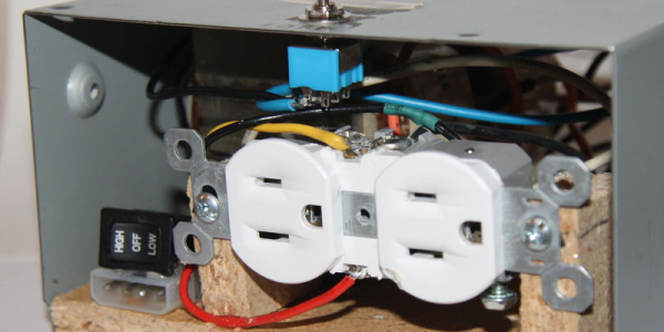
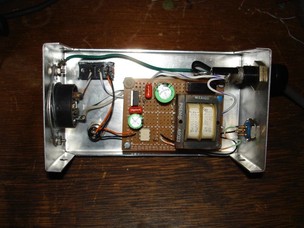
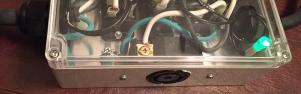
Of course, your dumpster transformer might be a little different than the one shown in the post (and the video, below). [Tanner] shows how to work out the leads you need. A little wood work and a PC power supply case finished the project.
Judging from the comments, some people take [Tanner’s] talk about safety as an implication that a transformer makes working on mains safe. It doesn’t. It makes it safer if you know what you are doing. Working with high voltage isn’t a place to learn by doing.
If you want some practical advice, [Jenny List] has a good read for you. You probably also ought to invest an hour in watching this video that has a lot of practical advice.
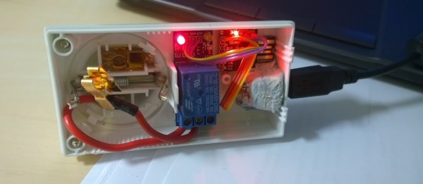
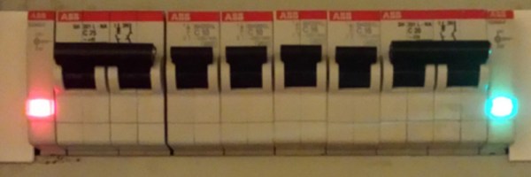
 The Internet of Things is fast approaching, and although no one can tell us what that actually is, we do know it has something to do with being able to control appliances and lights or something. Being able to control something is nice, but being able to tell if a mains-connected appliance is on or not is just as valuable. [Shane]