fiber matrix

Big LED Matrix Becomes Tiny LED Matrix Thanks To Fiber Optics

Everyone loves LED matrices, and even if you can’t find what you like commercially, it’s pretty easy to make just what you want. Need it big? No problem; just order a big PCB and some WS2812s. Need something tiny? There are ridiculously small LEDs that will test your SMD skills, as well as your vision.

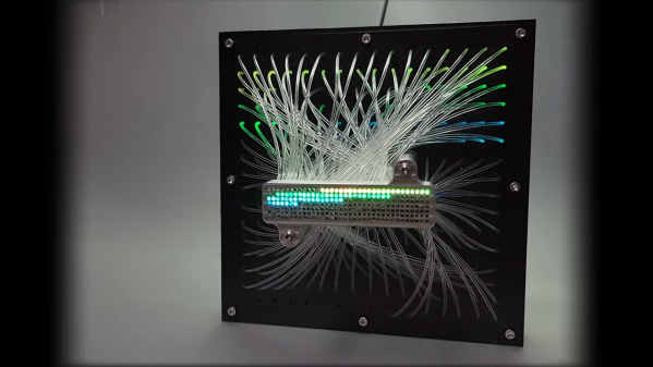
But what if you want a small matrix that’s actually a big matrix in disguise? For that, you’ll want to follow [elliotmade]’s lead and incorporate fiber optics into your LED matrix. The build starts with a 16×16 matrix of WS2812B addressable LEDs, with fairly tight spacing but still 160 mm on a side. The flexible matrix was sandwiched between a metal backing plate and a plastic bezel with holes directly over each LED. Each hole accepts one end of a generous length of flexible 1.5-mm acrylic light pipe material; the other end plugs into a block of aluminum with a 35 by 7 matrix of similar holes. The small block is supported above the baseplate by standoffs, but it looks like the graceful bundle of fibers is holding up the smaller display.

A Raspberry Pi Pico running a CircutPython program does the job of controlling the LEDs, and as you can see in the video below, the effect is quite lovely. Just enough light leaks out from the fibers to make a fascinating show in the background while the small display does its thing. We’ve seen a few practical uses for such a thing, but we’re OK with this just being pretty. It does give one ideas about adding fiber optics to circuit sculptures, though.

Continue reading “Big LED Matrix Becomes Tiny LED Matrix Thanks To Fiber Optics”

Digital Rain Animation Crammed Into Pi Pico

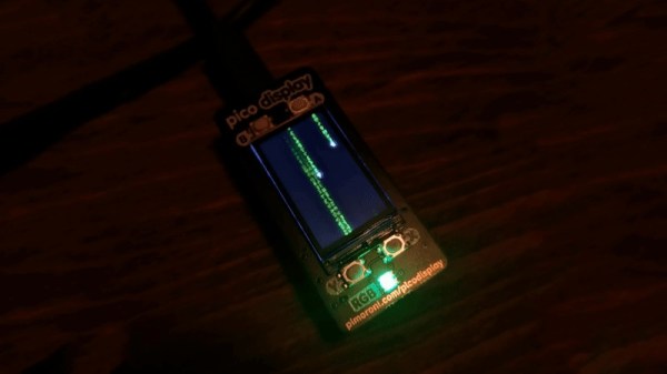
With a new Matrix movie now in cinemas, we’ve all been reminded of those screensavers that were just the coolest thing ever when the original film dropped in 1999. [en0b] decided to recreate the classic “digital rain” effect on the Raspberry Pi Pico, using up all the little microcontroller’s storage in the process.

Rather than rely on existing graphics libraries, [en0b] set about using a high-quality GIF for the animation. The original file was 8 MB, which was far too big to fit on the Pico. After some finagling in an image editor and with the help of a custom Python script, however, [en0b] managed to fit the 127-frame animation at 240 x 135 resolution into the 2 MB Flash onboard the chip. With the microcontroller hooked up to the 1.14″ IPS “Pico Display” from Pimoroni, the final looks great and faithfully recreates the aesthetic seen in the film.

[en0b]’s technique could reliably be used for displaying any GIF that you can cut down to 14 to 16 colors without losing too much quality. It’s not the world’s highest-end graphics format, but it does the job for little animations like these.

We’ve seen similar builds before too, using more heavy-duty hardware to build a magic 8-ball in much the same way. Meanwhile, if you’ve got your own neat little GIF hacks or Pico projects, don’t hesitate to send them in!

Tileable LED matrix

Tiny LED Matrix Panels Tile Together Perfectly

There’s a lot to admire about LED matrix projects, which more often than not end up looking really cool. But most of them rely on RGB matrix panels sourced from the surplus market, and while there’s nothing wrong with that, building your own tiny, tileable LED matrix panels makes these builds just a little bit cooler.

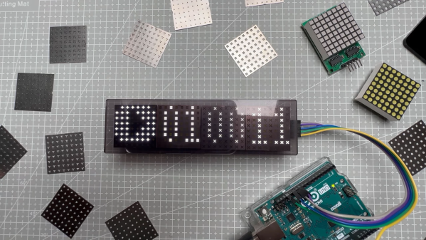
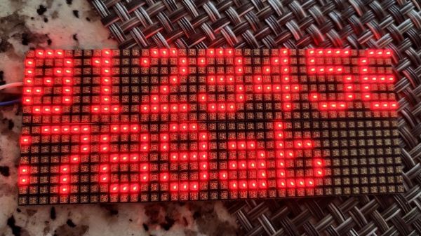
There’s a lot to admire about these matrix panels, not least of which is the seamless way they tile together. But to get to that point, [sjm4306] had a lot of prep work to do. He started with a much simpler 5×7 array, using the popular WS2812 RGB LEDs on a custom PCB. With a little practice under his belt, it was time to move to the much smaller SK6805 LEDs, which were laid out in an 8×8 matrix. The board layout is about as compact as it can be; [sjm4306] reports that it pushed the PCB fab to their limits, but he ended up with LEDs spaced perfectly on the board and just enough margin to keep consistent spacing in two dimensions when the boards are adjacent to each other.

Assembly of the boards was challenging, to say the least. The video below shows that the design left barely enough room for handling the LEDs with tweezers, and some fancy finagling was needed to get the boards on and off the hotplate for reflow. [sjm4306] says that he’ll be exploring JLC PCB’s assembly service in the future, since each board took an hour for him to assemble. But they look fantastic when daisy-chained together, with no detectable gaps at the joints.

With matrices like these, the possibilities are endless. We’ve even got a whole list of LED matrix projects over on Hackaday.io for you to check out.

Continue reading “Tiny LED Matrix Panels Tile Together Perfectly”

Enter The Matrix With This Custom PC Side Panel

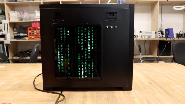
With a new Matrix movie out now, it’s hardly a surprise that we’re starting to see more and more projects centered around the franchise’s iconic “Digital Rain” effect. A few particularly unique examples have floated to the top of this virtual tsunami of green-tinted sushi recipes, such as this very slick RGB LED PC side panel built by [Will Donaldson].

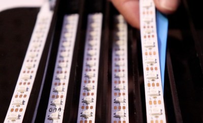
In place of the normal clear window in his PC case, [Will] has mounted a black acrylic sheet that has had all of the “code” characters laser-cut from it. Behind that is an array of WS2812B LED strips, nestled into vertically aligned channels that keep the light from bleeding out horizontally. A sheet of frosted plastic is sandwiched between the two, which helps diffuse the light so the individual LEDs aren’t as visible.

All of the LEDs are connected to a NodeMCU ESP8266 by way of a 74AHCT125 level-shifter, though [Will] notes you could certainly use a different microcontroller with some tweaks to the code. As it stands, the user selects from various lighting patterns using two potentiometers and a button that have been mounted next to the panel. But if you were so inclined, it certainly wouldn’t take much to adapt the firmware so that the lighting effects could be triggered from the PC.

The sticklers will note that this means the characters can’t actually change or move, but as you can see in the video below, it still looks quite impressive when the LEDs get going behind them. If you’re looking to recreate the look on a considerably smaller scale, check out this Arduino library that can make it rain on a TFT display with just a few lines of code.

Continue reading “Enter The Matrix With This Custom PC Side Panel”

Arduino Library Makes Digital Rain Like It’s 1999

There’s going to be a new Matrix movie in theaters next month, and you know what that means: we’re about to see a whole new generation get obsessed with the franchise’s iconic “Digital Rain” effect. Thanks to modern advertisement technology, expect to see lines of glittering text pouring down the displays of everything from billboards to gas pumps pretty soon.

Doesn’t get much easier than that.

For those of us who’ve just been looking for an excuse to break out the old Matrix screensavers, you might as well get a jump on things using this handy Arduino library for the ESP8266 and ESP32. Developed by [Eric Nam], it lets you start up a digital rainstorm on displays supported by the TFT_eSPI library as easily as running digitalRainAnim.loop().

You can even install the library through the Arduino IDE, just open the Library Manager and search for “Digital Rain” to get started. You’ve still got to hook the display up to your microcontroller, but come on, [Eric] can’t do it all for you.

Looking at the examples, it seems like various aspects of the animation like color and speed can be configured by initializing the library with different values. Unfortunately we’re not seeing much in the way of documentation for this project, but by comparing the different examples, you should be able to get the high points.

While our first choice would certainly be a wall of green alphanumeric LED displays, we can’t help but be impressed with how easy this project makes it to spin up your own little slice of the Matrix on the workbench.

Continue reading “Arduino Library Makes Digital Rain Like It’s 1999”

Improved Technique For Resistive Divider Keypads

[Lauri Pirttiaho] from the [Swiss Knife of Electronics] channel explains how to simplify your resistive divider keypad design on Hackaday.io.

The usual method involves building a resistive ladder that gives unique and equally spaced voltages for each keypress. If you have just four or five discrete buttons, it isn’t terribly difficult, but if you have a 12- or 16-keypad matrix, things get complicated. [Lauri] looked into the past to come up with a better way, specifically a 646 page, 1 kg textbook from 1990 — Analogue Ic Design: The Current-Mode Approach by Toumazou, Lidgey, and Haigh. He learned that sometimes what’s hard to do in the voltage domain is easy in the current domain.

Normally you’d throw in some resistors to form different voltage dividers depending on which key is pressed, and read the resulting voltage off of a voltage divider with an ADC. But that means using the voltage divider equation, and the difference in voltage between keys can get very small. Dropping the voltage divider and measuring the current through a current mirror generates a linear voltage across its output load resistor that can be easily read by your microprocessor. And [Lauri] has posted an example of just such a program on his GitHub repository for an Arduino.

Heavy analog electronics, for sure, but something to keep in mind if you’re reading more than 12 keys. Do you have any examples of solving problems by looking into old and/or less-common techniques? Let us know in the comments below.

Continue reading “Improved Technique For Resistive Divider Keypads”

This Slimline Word Clock Uses Laser Etching To Keep Things Simple

Judging by the tips we get, it seems like the popularity of word clocks has perhaps started falling off lately. But back at peak word clock, we were seeing dozens of designs, some better than others. This simple but classy word clock seems to benefit from all that prior art, making the design just about as simple as it can get while still looking great.

The main tool for [t0mg]’s build is a laser cutter, which is a great choice for keeping the design simple. The tricky part of word clocks is getting the “word search” matrix executed cleanly, and we’ve seen everything from laser-cut wood to inkjet prints, and even commercially produced PCBs, used for the job. [t0mg] opted instead to spray paint a piece of glass and etch away the characters with the laser, which results in superb text quality. Etching the underside of the glass also has the advantage of protecting the paint layer while giving the finished clock a glossy face that really looks nice. Under the template lie layers of MDF that hold the Neopixel strips and act as light guides, while an ESP32 and RTC perform timekeeping and LED-driving duties. [t0mg] finished off the clock with a nice web interface to set the clock, change the colors, and perform maintenance functions. The video below shows the software in use.

We really think this clock looks great, and for those with access to a laser cutter, it seems like a great way to go about building your own.

Continue reading “This Slimline Word Clock Uses Laser Etching To Keep Things Simple”