74-Series Clock Gets A MEMS Heart

[Erik van Zijst] has had a long career as a programmer, but lacked an understanding of what was happening at a bare metal level. After building a few logic gates out of transistors to get a feel for electronics, he set out to build a working clock using 74-series logic. Naturally, it was quite the adventure. 

The project starts out as many do on the breadboard. The requisite BCD counters and 7-segment displays were sourced, and everything was connected up with a cavalcade of colorful hookup wires. A 32.768 KHz crystal was pressed into service to generate the clock signal, divided down to get a 1Hz output to drive the seconds counter that would then run the entire clock. [Erik] then had to learn some more practical electronics skills, to deal with debouncing buttons for the time setting circuit.

With the clock now functional, [Erik] decided to take things further, aiming to build something more robust and usable. An automatic brightness control was created using a 555 to run a crude PWM dimmer for the LEDs. Additionally, a PCB was designed to replace the temporary breadboard setup. This led to problems with the oscillator that [Erik] couldn’t quite figure out. Rather than continue on the same path, he changed tack, instead replacing the quartz crystal with a modern MEMS oscillator that solved the problem.

It’s a great look at how to construct a working clock from bare logic, and one that serves to remind us just how complex even a seemingly simple device can be. We’ve seen other from-scratch builds before too, like this 777-transistor clock, or this attractive stacked design. Video after the break.

Continue reading “74-Series Clock Gets A MEMS Heart”

How Safe Is That Ultrasonic Bath For Flux Removal?

How do you clean the residual flux off your boards? There are plenty of ways to go about the job, ranging from “why bother?” to the careful application of isopropyl alcohol to every joint with a cotton swab. It seems like more and more people are turning to ultrasonic cleaners to get the job done, though, and for good reason: just dunk your board and walk away while cavitation does the work for you.

But just how safe is it to sonically blast the flux off your boards? [SDG Electronics] wanted to know, so he ran some cleaning tests to get to the bottom of things. On the face of it, dunking a PCB in an aqueous cleaning solution seems ill-advised; after all, water and electricity famously don’t mix. But assuming all the nooks and crannies of a board can be dried out before power is applied, the cleaning solution itself should be of little concern. The main beef with ultrasonic cleaning seems to be with the acoustic energy coupling with mechanical systems on boards, such as crystal oscillators or micro-electrical-mechanical systems (MEMS) components, such as accelerometers or microphones. Such components could resonate with the ultrasonic waves and be blasted to bits internally.

To test this, [SDG Electronics] built a board with various potentially vulnerable components, including the popular 32.768-kHz crystal, cut for a frequency quite close to the cleaner’s fundamental. The video below goes into some detail on the before-and-after tests, but the short story is that nothing untoward happened to any of the test circuits. Granted, no components with openings as you might find on some MEMS microphones were tested, so be careful. After all, we know that ultrasound can deal damage, and if it can levitate tiny styrofoam balls, it might just do your circuit in.

Continue reading “How Safe Is That Ultrasonic Bath For Flux Removal?”

Balance Box Game Requires A Steady Hand

In the distant past, engineers used exotic devices to measure orientation, such as large mechanical gyros and mercury tilt switches. These are all still useful methods, but for many applications MEMS motions devices have become the gold standard. When [g199] set out to build their Balance Box game, it was no exception.

The game consists of a plastic box, upon which a spirit level is fitted, along with a series of LEDs. The aim of the game is to keep the box level while carrying it to a set goal. Inside, an Arduino Uno monitors the output of a MPU 6050, a combined accelerometer and gyroscope chip. If the Arduino detects the box is tilting, it warns the user with the LEDs. Tilt it too far, and a life is lost. When all three lives are gone, the game is over.

It’s a cheap and simple build that would have been inordinately more expensive only 10 to 20 years ago. It goes to show the applications enabled by ubiquitous cheap electronics like MEMS sensors. The technology has other fun applications, too – for example the Stecchino game, or this giant balance board joystick. We’re certainly lucky to have such powerful technology at our fingertips!

A Petite Pico Projector For Portable Pi

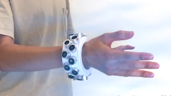
A few years ago, new, innovative pico projectors, influenced by one of the TI development kits, started appearing in Kickstarter projects and other various DIY endeavours. Those projects fizzled out, most likely due to the cost of the projectors, but we got a few laughs out of it: that wearable smartphone that projected a screen onto your wrist used the same technology.

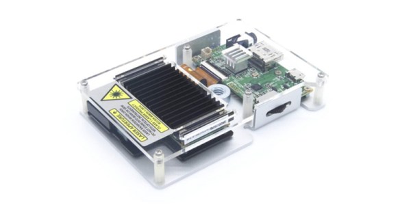
But there’s a need for a small projector, a pico projector, or in this case a femto projector. It’s the Nebra Anybeam, and it’s a small projector that uses lasers, and it comes in the form of a Raspberry Pi hat. We would like to congratulate the team for shipping the ideal use case of their product first.

The key features of this pico projector address the shortcomings of existing projectors that can fit in your pocket. This uses a laser, and there’s no bulb, and the power consumption can be as low as 3 Watts. Power is provided over a micro USB cable. The resolution of this projector is 720p, which is sufficient for a quick setup for watching a movie, but the brightness is listed as equivalent to 150 ANSI lumens, about the same as small projectors from a few years ago.

But of course the big selling point isn’t the brightness or resolution, it’s all about the smallness of the projector itself. There is a developer’s kit, a Pi Hat, a fit-in-your-pocket version with an enclosure, and a ‘monster ball’ version of the Anybeam.

Do You Know Where Your Drone Is Headed? HJWYDK Article Explores Limits Of MEMS Sensors

Knowing in what absolute direction your robot is pointed can be crucial, and expensive systems like those used by NASA on Mars are capable of calculating this six-dimensional heading vector to within around one degree RMS, but they are fairly expensive. If you want similar accuracy on a hacker budget, this paper shows you how to do it using cheap MEMS sensors, an off-the-shelf motion co-processor IC, and the right calibration method.

The latest article to be published in our own peer-reviewed Hackaday Journal is Limits of Absolute Heading Accuracy Using Inexpensive MEMS Sensors  (PDF). In this paper, Gregory Tomasch and Kris Winer take a close look at the heading accuracy that can be obtained using several algorithms coupled with two different MEMS sensor sets. Their work shows that when properly used, inexpensive sensors can produce results on par with much more costly systems. This is a great paper that illustrates the practical contributions our community can make to technology, and we’re proud to publish it in the Journal.

Continue reading “Do You Know Where Your Drone Is Headed? HJWYDK Article Explores Limits Of MEMS Sensors”

Casio Watch Gets A MEMS Oscillator Upgrade

We’ve got to admit to being a bit of a Casio G-Shock watch geek. The big, chunky watches were every day carry items that survived everything we dished out, right up until the smartphone made wearing one seem redundant. But others continue to use and abuse G-Shocks, and some brave souls even hack them.

Replacing the standard quartz crystal with a temperature-compensated MEMS oscillator is one hack that [Alex] tried, and it appears to have worked out well. His project write-up doesn’t specify which MEMS oscillator was used, but we suspect it’s the SiT1552 TCXO. With its extremely small size, stability over a wide range of temperatures, and ultra-low power requirements, the chip is a natural choice to upgrade the stock 32.768-kHz quartz crystal of the watch. Trouble is, the tiny 1.5 mm x 0.8 mm chip-scale package (CSP) device presented some handling problems. After overcooking a few chips in the reflow oven, [Alex] was able to get one mounted to a tiny breakout board, which went into the space formerly occupied by the watch’s quartz crystal. He stole power for the TCXO from a decoupling capacitor, sealed the watch back up, and it’s back in service with better stability and longer battery life to boot. The video below shows the TCXO undergoing tests alongside the original quartz crystal and a comparatively huge DS3231 RTC module, just for fun.

[Alex]’s MEMS transplant seems a long way to go and a lot of fussy work for marginal gains, but who are we to judge? And it does make the watch susceptible to punking with a little helium, which might make things interesting.

Continue reading “Casio Watch Gets A MEMS Oscillator Upgrade”

Piezoelectric Gyro Shows How They Rolled Back In The Day

There’s no doubting the wonders that micro-electromechanical systems (MEMS) technology have brought to the world. With MEMS chips, your phone can detect the slightest movement, turning it into a sensitive sensor platform that can almost anticipate what you’re going to do next. Actually, it’s kind of creepy when you think about it.

But before nano-scale MEMS inertial sensing came along, lots of products needed to know their ups from their downs, and many turned to products such as this vibrating piezoelectric gyroscope that [Kerry Wong] found in an old camcorder. The video below shows a teardown of the sensor, huge by MEMS standards but still a marvel of micro-engineering. The device is classified as a Coriolis vibratory gyroscope (CVG) which, as the name implies, uses the Coriolis effect to sense rotation. In this device, [Kerry] found that a long, narrow piezoelectric element spans the long axis of the sensor, suspended from what appears to be four flexible arms. [Kerry] probed the innards of the sensor while powered up and discovered a 22 kHz signal on the piezo element; this vibrates the bar in one plane so that when it rotates, it exerts a force on the support arms that can be detected. Indeed, [Kerry] hooked the output of the sensor to a wonderfully old-school VOM whose needle wiggled with the slightest movement of the sensor.

Sadly, MEMS made this kind of sensor obsolete, but we appreciate the look under the hood. And really, MEMS chips are using the same principle to detect motion, just on a much smaller scale. Want the MEMS basics? [Al] has you covered.

Continue reading “Piezoelectric Gyro Shows How They Rolled Back In The Day”