When working with hardware, whether a repair or a fresh build, it’s often necessary to test something. Depending on what you’re working with, this can be easy or a total pain if you can’t get the right signal to the right place. To eliminate this frustrating problem, [WilkoL] built a useful pulse generator for use in the lab.
[WilkoL] notes that historically, the job of generating pulses of varying length and frequency would be achieved with a smattering of 555 timers. While this is a perfectly cromulent way to do so, it was desired to take a different approach for the added flexibility modern hardware can offer. The pulse generator is instead built around an STM8 microcontroller; an unusual choice in this era, to be sure. [WilkoL] specified the part for its incredibly low cost, and highly capable timer hardware – perfect for the job.
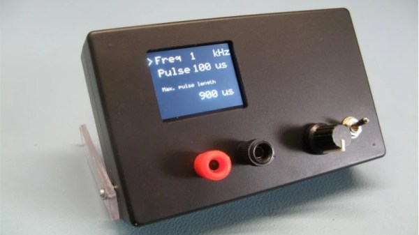
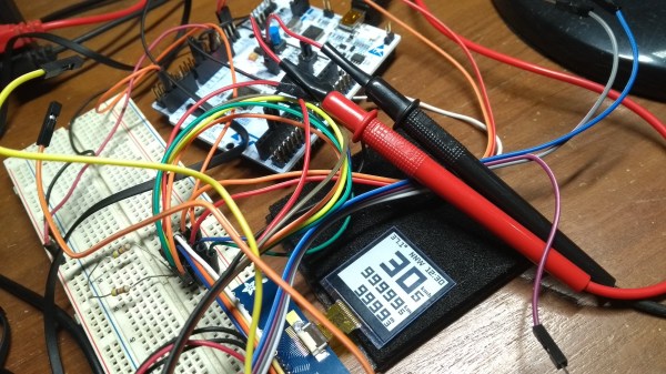
Combined with an ST7735 TFT LCD screen, and programmed in bare metal for efficiency’s sake, the final project is installed in a project box with controls for frequency and pulse length – no more, no less. Capable of pulse lengths from 250 ns to 90 s, and frequencies from 10 mHz to 2 MHz, it’s a tool that should be comfortable testing everything from servos to mechanical counters.
Of course, if you need to get down to picosecond timescales, an avalanche pulse generator might be more your speed. Video after the break.
Continue reading “Pulse Generator Does The Job With An STM8”


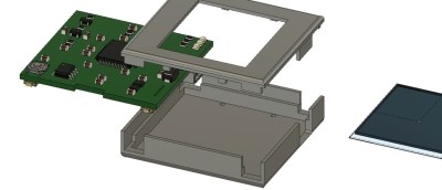 The brains are an STM32L476 low-power controller, and there is a Sharp Memory LCD display as it is a nice compromise between fast refresh rate and low power. E-paper would be a nice choice for outdoor readability (and obviously low power as well) but nothing worse than a laggy speedometer or compass.


