Hacklet 119 – Retrogaming Console Hacks

If you haven’t heard, retrogaming is a thing. 40-somethings are playing the games of their youth alongside millennials who are just discovering these classic games. There are even folks developing new homebrew games for consoles as far back as the Nintendo Entertainment System and the Atari 2600. This week on the Hacklet, we’re highlighting some of the best retrogaming console hardware hacks on Hackaday.io. Note that I did say hardware hacks. The focus this week is on games played on the original hardware. Don’t worry though, I’ll give emulated projects some love in a future Hacklet.
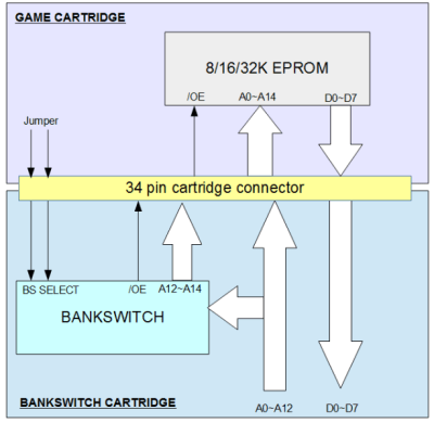
bankerWe start with [danjovic] and Atari 2600 Bankswitch Cartridge. The Atari 2600 is a legendary system. Millions of hackers’ first exposure to gaming came through its one button joystick. To make the unit affordable, Atari used a MOS Technology 6507 processor. Essentially it’s a 6502 in a 28-pin package. This meant several features got nerfed, most notably the address space. The 6507 can only address 8KB of RAM. In the Atari, only 4KB is available to the cartridge. Games got around the 4KB limit by bank switching – write a value to a magic address, and the bank switching logic would swap in a whole different section of cartridge ROM. There were several different bank switching schemes used over the years. [Danjovic] has created his own version of this bank switching logic, using only classic 74 series logic chips.
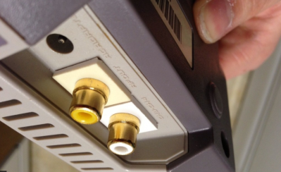
 

nesmodNext up is [ThunderSqueak] with Top Loader NES composite mod. Toward the end of the NES’s life, Nintendo introduced a cost-reduced version known as the “top loader”. This version had a top loading cartridge and no DRM lock-out chip. Unfortunately it also did away with composite AV ports. The only way to hook this NES to your TV was through the RF modulated output. [ThunderSqueak] and a number of other intrepid hackers have fixed this problem. All it takes is a 2N3906 PNP transistor and a few jellybean parts. The video and audio outputs are pulled from the motherboard before they enter the RF modulator. One nice feature is the clean connectors. [ThunderSqueak] used connectors from modular in-wall AV boxes for a setup that looks as good as it works.
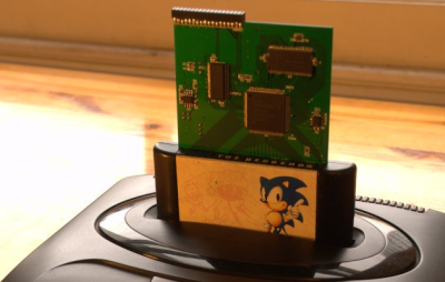
segaNext we have [makestuff] with USB MegaDrive DevKit. Sega’s MegaDrive, or Genesis as it was known here in the USA, was a groundbreaking console. It used a Motorola 68000 16-bit CPU while most other systems were still running a Z80 or a 6502. People loved this console, and there are plenty who still want to develop software for it. Enter [makestuff] with his development kit. On a card with a $40 USD bill of materials, he’s managed to fit SDRAM, an FPGA, and a USB interface. This is everything you need to load and debug software on an unmodified console. The FPGA had enough logic left over that [makestuff] was able to implement a continuous bus cycle tracer over USB. Nice work!
robbbFinally, we have our own [Joshua Vasquez] with R.O.B. 2.0. The original NES came in a deluxe version with a special pack in – a robot. Robotic Operating Buddy, or ROB for short, would play games with the player. Unfortunately ROB was a bit of a flop. It only worked with two games, Gyromite and Stack-Up Ice Climber. Most ROB units eventually found their way to the recycling bin. [Joshua] is building a new version of the ROB, with modern controls. He’s already modeled and 3D printed ROB’s head. I can’t wait to see this project come together!

If you want to see more retrogaming goodness, check out our new retrogaming hardware hacks list. See a project I might have missed? Don’t be shy, just drop me a message on Hackaday.io. That’s it for this week’s Hacklet, As always, see you next week. Same hack time, same hack channel, bringing you the best of Hackaday.io!

This NES Emulator Build Lets You Use Cartridges To Play Games

You may not remember this, but Nintendo hardware used to be a pretty big deal. The original Game Boy and NES both had remarkable industrial design that, like the Apple II and IBM Thinkpad, weren’t quite appreciated until many years after production ended. But, like many of you, [daftmike] had nostalgia-fueled memories of the NES experience still safely locked away.

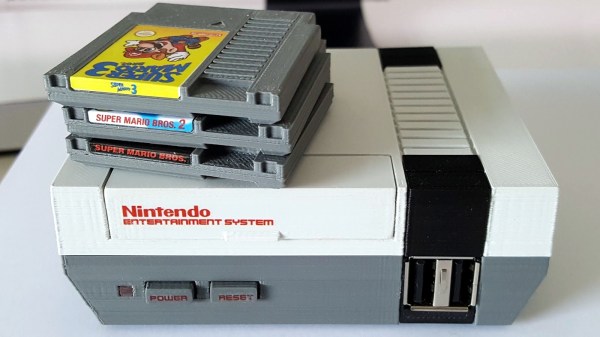
Memories like lifting the cartridge door, blowing on the cartridge, and the feel of the cartridge clicking into place. So, understandably, reliving those experiences was a key part of [daftmike’s] Raspberry Pi-based NES build, though at 40% of the original size. He didn’t just want to experience the games of his youth, he wanted to experience the whole NES just as he had as a child.

20160727_181746

Now, like any respectable hacker, [daftmike] didn’t let gaps in his knowledge stop him. This project was a learning experience. He had to teach himself a lot about 3D design and modeling, using Linux, and programming. But, the end result was surely worth the work; the attention to detail shows in features like the USB placement, the power and reset buttons, and of course the game cartridges which work with the magic of NFC and still include the insert and toggle action of the original cartridge carriage.

If you have a 3D printer and Raspberry Pi available, you could build a similar NES emulator yourself. But if you don’t have a 3D printer, but do have an original NES lying around, you could pull of the Raspberry Pi in a NES case hack. Whichever you do, the NES’s beauty deserves to be displayed in your home.

Continue reading “This NES Emulator Build Lets You Use Cartridges To Play Games”

Recreating Chiptunes In Verilog

The semester is wrapping up at Cornell, and that means it’s time for the final projects from [Bruce Land]’s lab. Every year we see some very cool projects, and this year is no exception. For their project, [Andre] and [Scott] implemented the audio processing unit (APU) of the Nintendo Entertainment System (NES). This is the classic chiptune sound that regaled a generation with 8-bit sounds that aren’t really eight bits, with the help of a 6502 CPU that isn’t really a 6502 CPU.

Unlike the contemporaneous MOS 6581 SID, which is basically an analog synthesizer on a chip, the APU in the NES is extraordinarily spartan. There are two pulse wave channels, a triangle wave channel, a random noise channel, and the very rarely used delta modulation channel (DMC) used to play very low quality audio samples. This is a re-implementation of the NES APU for a university lab; it is very understandable that [Andre] and [Scott] didn’t implement the rarely used DMC.

Everything about the circuitry of the NES is well documented, so [Andre] and [Scott] had a great wiki for their research. At the highest level, the APU runs on a 894kHz clock and controls three channels through dedicated registers. These outputs are fed through a mixer, which the guys scaled and combined into a 16-bit output played through a Wolfson WM8731 audio codec.

After implementing the NES APU, [Andre] and [Scott] added an SD card reader that can read the Nintendo Sound Format – the standard distribution format for NES chiptunes – and emulated a 6502 to control the registers. The result is a relatively simple device that plays NES chiptunes with amazing accuracy. The sound files on the project report sound like the real thing, but this is entirely emulated on modern hardware.

NES Light Gun Turned (Video) Synthesizer

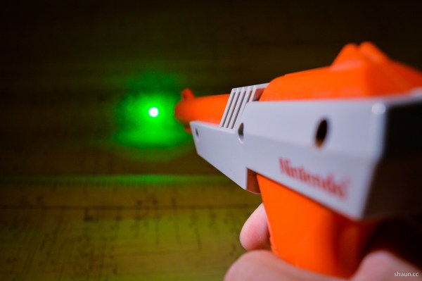
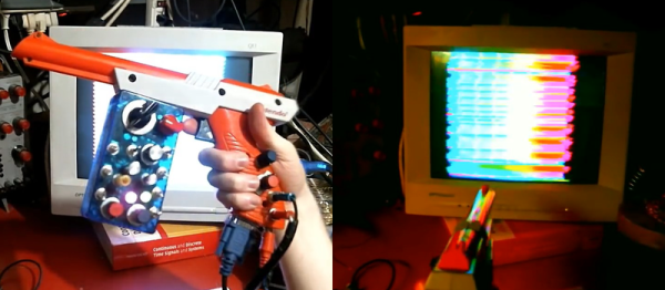
[Russell Kramer] made our day today. We’re tremendous fans of minimalism in electronics design, dirty noise hacks, and that old NES  light gun. He’s posted up a project that combines all three to make a light-gun controlled, VGA video display that makes bleepy-bloopy noises to boot. Check out the video below!

To appreciate this hack, you really need to read through the project logs in detail. Start with the VGA signal creation, for instance. The easiest way to go these days is to throw a microcontroller at the problem. But because he’s done that to death, [Russell] takes a step back thirty years and generates the sync pulses periodically with a relaxation oscillator and a binary counter IC. The rest of the build follows this aesthetic choice: everything is op amps and CMOS logic. The rainbow effect, for instance, is created from the audio signal through a three-stage, 120-degree phase-shift oscillator sent to the R, G, and B channels. Kudos!

The high-level overview is that the light intensity and position hitting the gun’s sensor is converted into a voltage that drives an audio-frequency oscillator. This audio output is then piped back into the video generator. Watching the video, it’s obvious that pointing the gun at different parts of the screen changes the pitch, but playing a given pitch is nearly impossible on this thing with all the feedback going on. [Russell] added a bit of more control into the system — when the gun’s trigger is pulled, it registers full-brightness regardless of the video input — but even so, we’d be hard-pressed to play “Mary Had a Little Lamb”.

But that’s not the point. The point is awesome, light-gun-waving noisy madness set to a responsive colorful video background. And that’s been achieved in spades!

Continue reading “NES Light Gun Turned (Video) Synthesizer”

Cleanest Rasberry Pi NES Mod

[ModPurist] sent us his Raspberry-Pi-in-a-Nintendo casemod. Before you go hitting the back button, this is a good one because it’s so well executed. And it’s actually a two-fer: he’d previously built up a wireless NES controller that completes the setup.

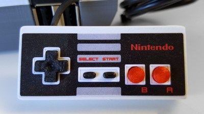
7058802Both of these mods are hacks in the purest sense of the word. The controller mod took a wireless keyboard’s sending circuit board and wedged it inside the NES controller. The original NES controller reads out the buttons into a shift register and sends that down a wire. That’s all gone. [ModPurist] just wired up each button to the sender PCB and figured out which keys they corresponded to on the PC by pressing the buttons. Simple.

The best part of his video about building the controller? After about a minute in, he forgets that he’s filming a technical how-to video and plays Pokemon for the remaining four minutes. That’s the sign of success.

Then there’s the NES hack itself. He stripped everything out, added a Raspberry Pi 2 and a fan, made it all work with the power switch and the original TV outs, and it’s done. Again, nothing more than needs doing, but nothing less. It looks just right plugged up to the CRT monitor (from a C64, no less), and there’s no doubt that being able to play wirelessly on an original NES controller is cool.

This isn’t [ModPurist]’s first time here on Hackaday either, and his “Cold Boy” fridge-turned-Gameboy is a work of art.

Continue reading “Cleanest Rasberry Pi NES Mod”

RGB LED Ceiling Display

yP8PoVDisco Floor’s are passé. [dennis1a4] turned them upside down and built an awesome RGB LED ceiling display using some simple hardware and a lot of elbow grease. His main room ceiling was exactly 32 ft x 20 ft and using 2 sq. ft tiles, he figured he could make a nice grid using 160 WS2812B RGB LEDs. A Teensy mounted in the ceiling does all the heavy lifting, with two serial Bluetooth modules connected to it. These get connected to two Bluetooth enabled NES game controllers. Each of the NES controller is stuffed with an Arduino Pro Mini, a Bluetooth module, Li-Ion battery and a USB charge controller.

Bluetooth is in non-secure mode, allowing him to connect to the Teensy, and control the LEDs, from other devices besides the NES controllers. The Teensy is mounted at the centre of the ceiling to ensure a good Bluetooth link. Programming required a lot of thought and time but he did manage to include animations as well as popular games such as Snake and Tetris.

LED_Ceiling_deadbugThe hard part was wiring up all of the 160 LED pixels. Instead of mounting the 5050 SMD LED’s on PCBs, [dennis1a4] wired them all up “dead bug” style. Each pixel has one LED, a 100nF decoupling capacitor, and 91 ohm resistors in series with the Data In and Data Out pins – these apparently help prevent ‘ringing’ on the data bus. Check the video for his radical soldering method. Each SMD LED was clamped in a machine shop vice, and the other three parts with their leads preformed were soldered directly to the LED pins.

The other tedious task was planning and laying out the wiring harness. Sets of 10 LEDs were first wired up on the shop bench. He then tacked them up to the ceiling and soldered them to the 14 gauge main harness. The final part was to put up the suspended ceiling and close the 2 sq. ft. grids with opaque plastic.

[dennis1a4]  did some trials to figure out the right distance between each LED and the panel to make sure they were illuminated fully without a lot of light bleeding in to adjacent panels. This allowed him to get away without using baffles between the tiles.

Check out the video to see a cool time-lapse of the whole build.

Continue reading “RGB LED Ceiling Display”