About Schmitt (Triggers)

There is an old saying: “In theory, theory and practice are the same. In practice, they are not.” We spend our time drawing on paper or a computer screen, perfect wires, ideal resistors, and flawless waveforms. Alas, the real world is not so kind. Components have all kinds of nasty parasitic effects and no signal looks like it does in the pages of a text book.

Consider the following problem. You have a sine wave input coming in that varies between 0 V and 5 V. You want to convert it to a square wave that is high when the sine wave is over 2.5 V. Simple, right? You could use a CMOS logic gate or a comparator. In theory…

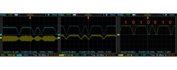
The problem is, the sine wave isn’t perfect. And the other components will have little issues. If you’ve ever tried this in real life, you’ll find that when the sine wave is right at the 2.5 V mark the output will probably swing back and forth before it settles down. This is exacerbated by any noise or stretching in the sine wave. You will wind up with something like this:

scope1

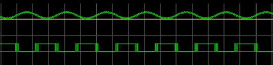
Notice how the edges of the square wave are a bit fat? That’s the output switching rapidly back and forth right at the comparator’s threshold.

Hysteresis

The answer is to not set the threshold at 2.5 V, or any other single value. Instead, impose a range outside of which it will switch, switching low when it leaves the low end of the range, and high when it exceeds the high end.  That is, you want to introduce hysteresis. For example, if the 0 to 1 shift occurs at, say, 1.9 V and the 1 to 0 switch is at 0.5 V, you’ll get a clean signal because once a 0 to 1 transition happens at 1.9 V, it’ll take a lot of noise to flip it all the way back below 0.5 V.

You see the same effect in temperature controllers, for example. If you have a heater and a thermal probe, you can’t easily set a 100 degree set point by turning the heater off right away when you reach 100 and then back on again at 99.9999. You will usually use hysteresis in this case, too (if not something more sophisticated like a PID). You might turn the heater off at 99 degrees and back on again at 95 degrees, for example. Indeed, your thermostat at home is a prime example of a system with hysteresis — it has a dead-band of a few degrees so that it’s not constantly turning itself on and off.

Schmitt Triggers and How to Get One

A Schmitt Trigger is basically a comparator with hysteresis. Instead of comparing the incoming voltage with VCC / 2, as a simple comparator would, it incorporates a dead band to ensure that logic-level transitions occur only once even in the presence of a noisy input signal.

Schmitt Trigger Symbol by Selket CC-BY 2.5

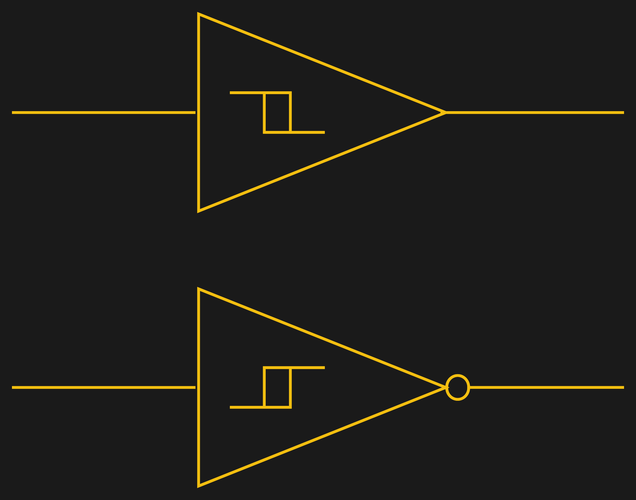
Assuming you want a Schmitt trigger in a circuit, you have plenty of options. There are ICs like the 74HC14 that include six (inverting) Schmitt triggers. On a schematic, each gate is represented by one of the symbols to the right; the little mark in the box is the hysteresis curve, and the little bubble on the output indicates logical negation when it’s an inverter.

You can also make them yourself out of transistors or even a 555 chip. But the easiest way by far is to introduce some feedback into a plain op amp comparator circuit.

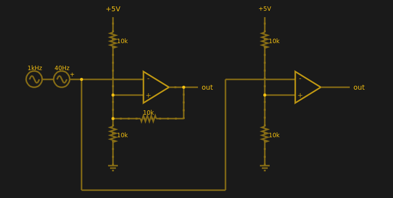
Below are two op amps, one with some positive feedback to make it act like a Schmitt trigger. The other is just a plain comparator. You can simulate the design online.


schem21-wide

If you haven’t analyzed many op amp circuits, this is a good one to try. First, imagine an op amp has the following characteristics:

  • The inputs are totally open.
  • The output will do whatever it takes to make the inputs voltages the same, up to the power supply rails.

Neither of these are totally true (theory vs. practice, again), but they are close enough.

The comparator on the right doesn’t load the inputs at all, because the input pins are open circuit, and the output swings to either 0 V or 5 V to try, unsuccessfully, to make the inputs match. It can’t change the inputs because there is no feedback, but it does make a fine comparator. The voltage divider on the + pin provides a reference voltage. Anything under that voltage will swing the output one way. Over the voltage will swing it the other way. If the voltages are exactly the same? That’s one reason you need hysteresis.

The comparator’s voltage divider sets the + pin to 1/2 the supply voltage (2.5 V). Look at the Schmitt trigger (on top). If the output goes between 0 V and 5 V, then the voltage divider winds up with either the top or bottom resistor in parallel with the 10K feedback resistor. That is, the feedback resistor will either be connected to 5 V or ground.

Of course, two 10K resistors in parallel will effectively be 5K. So the voltage divider will be either 5000/15000 (1/3) or 10000/15000 (2/3) depending on the state of the output. Given the 5 V input to the divider, the threshold will be 5/3 V (1.67 V) or 10/3 V (3.33 V). You can, of course, alter the thresholds by changing the resistor values appropriately.

Practical Applications

Schmitt triggers are used in many applications where a noisy signal requires squaring up. Noisy sensors, like an IR sensor for example, can benefit from a Schmitt trigger. In addition, the defined output for all voltage ranges makes it handy when you are trying to “read” a capacitor being charged and discharged. You can use that principle to make a Schmitt trigger into an oscillator or use it to debounce switches.

If you want to see a practical project that uses a 555-based Schmitt, check out this light sensor. The Schmitt trigger is just one tool used to fight the imprecision of the real world and real components. Indeed, they’re nearly essential any time you want to directly convert an analog signal into a one-bit, on-off digital representation.

The Kraakdoos — Musical Abuser Of An Ancient OpAmp

A friend from the newly founded Yeovil Hackerspace introduced me to a device known as “The Kraakdoos” or cracklebox.

The cracklebox is an early electronic instrument produced by STEIM in the 1970s. The instrument consists of a single PCB with a number of copper pads exposed on one side. The player touches the pads and the instrument emits… sounds which can perhaps best be described as squeeze and squeals.

While the cracklebox was original sold as a complete instrument, the device has been reverse engineered, and the schematic documented. What lies inside is quite fascinating.

The heart of the cracklebox is an ancient opamp, the LM709. The LM709 is the predecessor to the famous LM741. Unlike the 741 the 709 had no internal frequency compensation. Frequency compensation is used to intentionally limit the bandwidth of an opamp. As input frequency increases, the phase shift of the opamp also increases. This can result in undesirable oscillation, as the feedback network forms an unintentional phase-shift oscillator.

Most modern opamps have internal frequency compensation, but the 709 doesn’t. Let’s see how this is used in the cracklebox:

krackdoos_schRather than using the frequency compensation pins as intended the cracklebox just routes them out to pads. In fact the cracklebox routes almost all the pins on the opamp out to pads, including the inverting and non-inverting inputs. A single 1MOhm feedback resistor is used in a non-inverting configuration. However reports suggest the instrument can work without a feedback resistor at all!

Continue reading “The Kraakdoos — Musical Abuser Of An Ancient OpAmp”

Instrumentation Amplifiers with Bil Herd

Instrumentation Amplifiers And How To Measure Miniscule Change

These days there a large number of sensors and analog circuits that are “controller friendly” meaning that their output signal is easily interfaced to the built-in Analog to Digital Convertors (ADCs) often found in today’s micro-controllers. This means that the signals typically are already amplified, often filtered, and corrected for offset and linearity. But when faced with very low level signals, or signals buried in a larger signal an Instrumentation Amplifier may be what’s needed. The qualities of an Instrumentation Amplifier include:

  • A differential amplifier with high impedance and low bias current on both inputs.
  • Low noise and low drift when amplifying very small signals.
  • The ability to reject a voltage that is present on both inputs, referred to as Common Mode Rejection Ratio (CMRR)

Continue reading “Instrumentation Amplifiers And How To Measure Miniscule Change”

hassler_pcb

Annoy Your Enemies With The Hassler Circuit

[Craig] recently built himself a version of the “hassler” circuit as a sort of homage to Bob Widlar. If you haven’t heard of Bob Widlar, he was a key person involved in making analog IC’s a reality. We’ve actually covered the topic in-depth in the past. The hassler circuit is a simple but ingenious office prank. The idea is that the circuit emits a very high frequency tone, but only when the noise level in the room reaches a certain threshold. If your coworkers become too noisy, they will suddenly notice a ringing in their ears. When they stop talking to identify the source, the noise goes away. The desired result is to get your coworkers to shut the hell up.

[Craig] couldn’t find any published schematics for the original circuit, but he managed to build his own version with discrete components and IC’s. Sound first enters the circuit via a small electret microphone. The signal is then amplified, half-wave rectified, and run through a low pass filter. The gain from the microphone is configurable via a trim pot. A capacitor converts the output into a flat DC voltage.

The signal then gets passed to a relaxation oscillator circuit. This circuit creates a signal whose output duty cycle is dependent on the input voltage. The higher the input voltage, the longer the duty cycle, and the lower the frequency. The resulting signal is sent to a small speaker for output. The speaker is also controlled by a Schmitt trigger. This prevents the speaker from being powered until the voltage reaches a certain threshold, thus saving energy. The whole circuit is soldered together dead bug style and mounted to a copper clad board.

When the room is quiet, the input voltage is low. The output frequency is high enough that it is out of the range of human hearing. As the room slowly gets louder, the voltage increases and the output frequency lowers. Eventually it reaches the outer limits of human hearing and people in the room take notice. The video below walks step by step through the circuit. Continue reading “Annoy Your Enemies With The Hassler Circuit”

Demodulating BPSK31 With OpAmps And 555s

BPSK31 is an extremely popular mode for amateur radio operators; it’s efficient and has a narrow bandwidth and can be implemented with a computer sound card or an Arduino. Just like it says on the tin, it’s phase shift keying, and a proper implementation uses a phase detection circuit or something similar. [Craig] thought it would be fun to build an analog BPSK31 demodulator and hit upon the idea of doing this with amplitude demodulation. No, this isn’t the way you’re supposed to do it, but it works.

Data is transmitted via BPSK31 with a phase shift of 180 degrees being a binary 0, and no phase shift being a binary 1. [Craig]’s circuit uses an op-amp and a pair of diodes to do a full wave rectification of the signal, which basically makes a binary 1 logic high, and binary 0 logic low.

This rectified signal is then fed into a comparator, making the output go high when the signal is above 2V, and low when the signal is below 1V. That’s all you need to do to get bits out of the signal, all [Craig] had to do after that was figure out a way to sample it.

A 555 set up in astable mode running at 31.25 Hz provides the clock, synchronized with the signal by connecting the comparator’s output to the 555 trigger input. The timer clock ends up being slightly slower, but thanks to the varicode character set, the maximum number of binary ones the circuit will see is nine; every time the trigger sees a zero, the timer’s trigger is reset, re-synchronizing the receiver’s clock.

Yes, it’s a hack, and no, this isn’t how you’re supposed to receive PSK. It does, however, work, and you can thank [Craig] for that.

board

The Disintegrated Op Amp

741
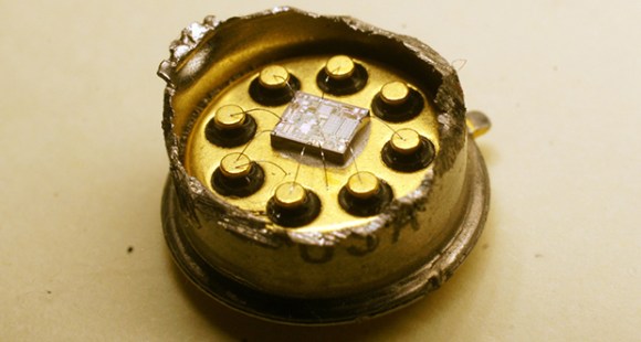
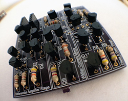
By now we’ve all seen the ‘Three Fives’ kit from Evil Mad Scientist, a very large clone of the 555 timer built from individual transistors and resistors. You can do a lot more in the analog world with discrete parts, and [Shane]’s SevenFortyFun is no exception: it’s a kit with a board, transistors, and resistors making a very large clone of the classic 741 op-amp, with all the parts laid bard instead of encapsulated in a brick of plastic.

[Shane] was inspired by the analog greats – [Bob Pease], [Jim Williams], and of course [Bob Widlar], and short of mowing his lawn with goats, the easiest way to get a feel for analog design was to build some analog circuits out of individual components.

[Shane] has a few more kits in mind: a linear dropout and switching regulators are on the top of the list, as is something like the Three Fives kit, likely to be used to blink giant LEDs.

Fake Audiophile Opamps Revealed

chip

The OPA627 is an old, popular, and very high-end opamp found in gear cherished by the most discerning audiophiles. This chip usually sells for at least $15, but when [Zeptobars] found a few of these expensive chips on ebay going for $2, his curiosity was piqued. Something just isn’t right here.

[Zeptobars] is well known for his decapsulating and high-resolution photography skills, so he cut the can off a real OPA627, and dissolved one of the improbably cheap ebay chips to reveal the die. Under the microscope, he found an amazing piece of engineering in the real chip – laser trimmed resistors, and even a nice bit of die art.

The ebay chip, if it were real, would look the same. It did not. The ebay chip only contained one laser trimmed resistor and looks to be a much simpler circuit. After a bit of research, [Zeptobars] found it was actually an AD774 opamp. The difference is small, but the AD774 still has much higher noise – something audiophiles could easily differentiate with their $300 oxygen-free volume knobs.

This isn’t the first instance of component counterfeiting [Zeptobars] has come across. He’s found fake FTDI chips before, and we’re counting the days until he gets around to putting a few obviously fake ebay 6581 SID chips under the microscope.