There’s no denying it. Super small robots are just cool. [Pinomelean] has posted an Instructable on how to create a mini line following robot using only analog circuitry. This would make a great demo project to show your friends and family what you’ve been up to.
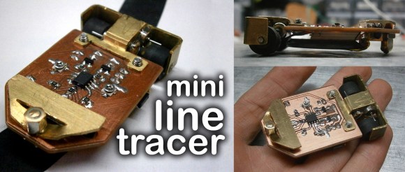
Analog circuitry can be used instead of a microcontroller for many different applications, and this is one of them. The circuit consists of two op-amps that amplify the output of two phototransistors, which control each motor. This circuit is super simple yet very effective. The mechanical system is also quite cool and well thought out. To keep things simple, the motors drive the wheel treads, rather than directly through an axle. After the build was completed, the device needed to be calibrated by turning potentiometers that control the gain of each op-amp. Once everything is balanced, the robot runs great! See it in action after the break.
While not the smallest line follower we have seen, this robot is quite easy to reproduce. What little robots have you build lately? Send us a tip and let us know!
[via Embedded Lab]