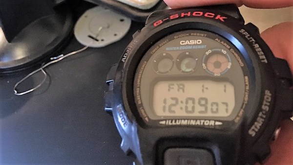
We’ve got to admit to being a bit of a Casio G-Shock watch geek. The big, chunky watches were every day carry items that survived everything we dished out, right up until the smartphone made wearing one seem redundant. But others continue to use and abuse G-Shocks, and some brave souls even hack them.
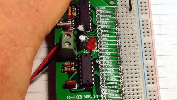
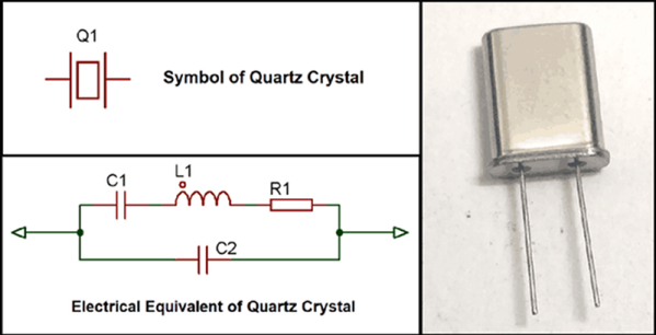
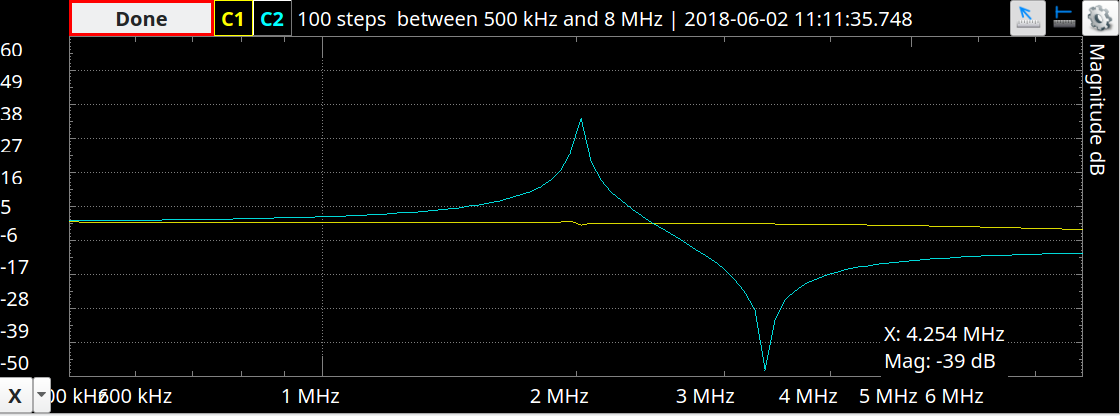
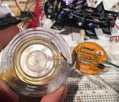
Replacing the standard quartz crystal with a temperature-compensated MEMS oscillator is one hack that [Alex] tried, and it appears to have worked out well. His project write-up doesn’t specify which MEMS oscillator was used, but we suspect it’s the SiT1552 TCXO. With its extremely small size, stability over a wide range of temperatures, and ultra-low power requirements, the chip is a natural choice to upgrade the stock 32.768-kHz quartz crystal of the watch. Trouble is, the tiny 1.5 mm x 0.8 mm chip-scale package (CSP) device presented some handling problems. After overcooking a few chips in the reflow oven, [Alex] was able to get one mounted to a tiny breakout board, which went into the space formerly occupied by the watch’s quartz crystal. He stole power for the TCXO from a decoupling capacitor, sealed the watch back up, and it’s back in service with better stability and longer battery life to boot. The video below shows the TCXO undergoing tests alongside the original quartz crystal and a comparatively huge DS3231 RTC module, just for fun.
[Alex]’s MEMS transplant seems a long way to go and a lot of fussy work for marginal gains, but who are we to judge? And it does make the watch susceptible to punking with a little helium, which might make things interesting.
Continue reading “Casio Watch Gets A MEMS Oscillator Upgrade”
 The visual and aural sensations of the video below will surely tempt you further, but in case it doesn’t, here’s a taste. When