While working on recreating an “ancient” (read: 60-year-old) logic circuit type known as resistor-transistor logic, [Tim] stumbled across a circuit with an unexpected oscillation. The oscillation appeared to be random and had a wide range of frequency values. Not one to miss out on a serendipitous moment, he realized that the circuit he built could be used as a chaotic oscillator.
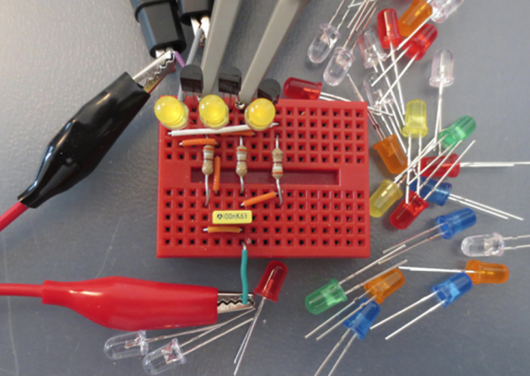
Chaotic systems can be used for, among other things, random number generation, so making sure that they do not repeat in a reliable way is a valuable property of a circuit. [Tim]’s design uses LEDs in series with the base of each of three transistors, with the output of each transistor feeding into the input of the next transistor in line, forming a ring. At certain voltages close to the switching voltages of the transistors, the behavior of the circuit changes unpredictably both in magnitude and frequency.
Building real-life systems that exhibit true randomness or chaotic behavior are surprisingly rare, and even things which seem random are often not random enough for certain applications. [Tim]’s design benefits from being relatively simple and inexpensive for how chaotic it behaves, and if you want to see his detailed analysis of the circuit be sure to visit his project’s page.
If you want to get your chaos the old fashioned way, with a Chua circuit, look out for counterfeit multipliers.