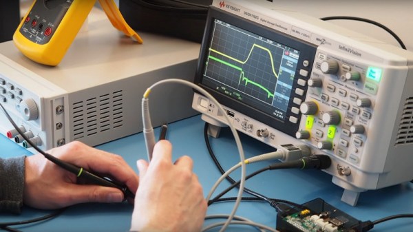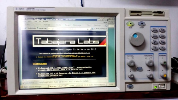
In the world of oscilloscopes, as in the rest of the test equipment world, there’s always some trickery afoot. Companies will often offer different models to the market at different price points, in an effort to gain the widest possible customer base while also making the most profit. Cheaper, less capable models are often largely identical to more expensive hardware, save for some software or a couple jumpers that disable functionality. [Alexandre] found just this when working to repair his HP 16533A scope card.
Work began when [Alexandre] received his HP 16533A in the mail after a long wait, only to find the trigger functionality was inoperable. This is crucial on a digital scope, so this simply wouldn’t do. After some research online, a post was found discussing which signals to probe to troubleshoot the issue. It noted that corrosion is a common problem on these units, and that occasionally, a certain resistor goes open circuit and causes problems. Initial measurement showed there was still resistance there, but reading closer, [Alexandre] noted this fateful line:
You might not be able to measure it accurately in circuit.
Removing the 100K resistor from the board, the part was indeed open circuit. After replacement with a new component, the trigger circuit was again fully operational. With the scope still open, it was then a simple job to execute a further resistor swap which gives the 16533A the functionality and range of the higher-spec 16534A model.
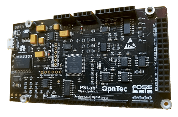
It’s very common for oscilloscopes and other test hardware to be configured this way from the factory. Rigol scopes are particularly popular with hackers for this very reason.
[Thanks to jafinch78 for the tip!]