Absolute Power

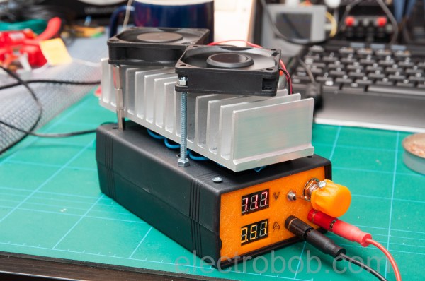
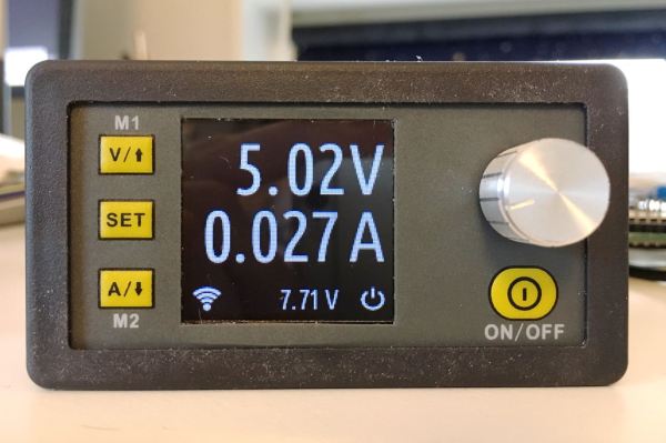
We recently noticed a very cool-looking series of power supply modules on a few of the Chinese deal web sites. Depending on the model, they provide a digitally-controlled voltage with metering. You need to provide at least a volt or so over the maximum desired output voltage. You can see a video from [iforce2d] below. The module in the video is rated for 5A at 50V maximum, but there are other sizes available. For those interested in graphs and numbers [lgyte] did a lot of characterization of these modules.

There was a time when importing goods from far away places was somewhat of an art. Finding suppliers, working out payment, shipping, and customs meant you had to know what you were doing. Today, you just surf the web, find what you want, pay with PayPal, and stuff shows up on your doorstep from all four corners of the globe.

There is one problem, though. We see a lot of cool stuff from China and some of it is excellent, especially for the price. Frankly, though, some of it is junk. It is hard to tell which is which. What’s more is even though in theory you might be able to return something, usually the freight charges make that impractical. So when you get a dud, you are likely to just eat it and chalk it up to experience. So the question is: how good (or bad) or these power supply modules?

Continue reading “Absolute Power”

Build The Simplest Bipolar Power Supply

How many integrated circuits do you need to build up a power supply that’ll convert mains AC into a stable DC voltage? Would you believe, none? We just watched this video by [The Current Source] (embedded below), where he builds exactly that. If you’re in the mood for a very well done review of diode bridges as well as half- and full-wave rectifiers, you should check it out.

First off, [TCS] goes through the basics of rectification, and demonstrates very nicely on the oscilloscope how increasing capacitance on the output smooths out the ripple. (Hint: more is better.) And then it’s off to build. The end result is a very simple unregulated power supply — just a diode bridge with some capacitors on the output — but by using really big capacitors he gets down into the few-millivolt range for ripple into a constant load.

The output voltage of this circuit will depend on the average current drawn, but for basically static loads this circuit should work well enough, and the simplicity of just tossing gigantic capacitors at the problem is alluring. (We would toss in a linear regulator somewhere.)

Quibbling over circuit designs isn’t why you’re watching this video, though. It’s because you want to learn something. Check out the rest of his videos as well. [TCS] has only been at it a little while, but it looks like this is going to be a channel to watch.

https://www.youtube.com/watch?v=0iDCsrMM7M0

Build Your Own Import Variable Lab Bench Power Supply

Does it ever just kill you that someone in a factory somewhere got to have all the fun of assembling your bench tools? There are a lot of questionable circuit boards floating around the Internet, and they can replicate practically any section of a circuit. When it comes to putting a prototype these days you can pretty much just buy each block of your system’s overview flowchart and string them together. [GreattScott!] combines a few of these into a relatively useful variable power supply with current limiting.

Admittedly, this is more of academic exercise if your only metric for success is monetary savings. Comparable power supplies can be purchased for the same amount of local currency as the parts in this build. However, there is something to be said for making it yourself.

The core of this build is based around the LTC3780, a bit of silicon from LT that offers both buck and boost converting along with a current control mode. It’s useful for a lot of things. The here is rated for up to 130 watts of power, which makes is a decent amount of power for a bench supply.

With a few modifications, like replacing the world’s most untrustworthy potentiometers and adding a nice ABS box, the build is completed. Along the way, [GreatScott!] offers a few tricks for testing and some reminders of how not to make yourself dead when playing with electricity.

The end is a working lab bench supply project that can easily keep a hacker entertained on a lazy Sunday afternoon.

Continue reading “Build Your Own Import Variable Lab Bench Power Supply”

Taking The Converted PC PSU Bench Supply A Step Further

A quality bench power supply is essential for electronics work. Nobody wants to go through the trouble of digging through their electronics bin just to find a wall wart with the right output. And, even if you were so inclined, it would be folly to assume that its output would actually be clean.

You could, of course, purchase a purpose-built bench power supply. But, this is Hackaday, and I’m sure many of you would rather build one yourself from an inexpensive PC power supply. Normally, you’d do this by separating out the different voltage lines into useful groups, such as 12V, 5V, and 3.3V. [Supercap2f] wanted to take this a step further, both to get a more useful unit and to practice his PCB-making.

His design uses a custom circuit design to fuse the circuits, and to provide some basic logic. Using the LCD display, you can see which lines are powered on. There is even a simple 3D printed cover to keep everything neat and tidy. [Supercap2f] has posted all of the design files, so you can build one of these yourself. We’ve seen similar builds in the past, but this is another nice one that anyone with the ability to etch PCBs can build.

Re-Capping An Ancient Apple PSU

It sometimes comes as a shock when you look at a piece of hardware that you maybe bought new and still consider to be rather high-tech, and realise that it was made before someone in their mid-twenties was born. It’s the moment from that Waylon Jennings lyric, about looking in the mirror in total surprise, hair on your shoulders and age in your eyes. Yes, those people in their mid-twenties have never even heard of Waylon Jennings.

[Steve] at Big Mess o’Wires has a Mac IIsi from the early 1990s that wouldn’t power up. He’d already had the life-expired electrolytic capacitors replaced on the mainboard, so the chief suspect was the power supply. That miracle of technology was now pushing past a quarter century, and showing its age. In case anyone is tempted to say they don’t make ’em like they used to, [Steve]’s PSU should dispel the myth.

It’s easy as an electronic engineer writing this piece to think: So? Just open the lid, pop out the old ones and drop in the new, job done! But it’s also easy to forget that not everyone has the same experiences and opening up a mains PSU is something to approach with some trepidation if you’re not used to working with line power. [Steve] was new to mains PSUs and considered sending it to someone else, but decided he *should* be able to do it so set to work.

The Apple PSU is a switch-mode design. Ubiquitous today but still a higher-cost item in those days as you’ll know if you owned an earlier Commodore Amiga whose great big PSU box looked the same as but weighed ten times as much as its later siblings. In simple terms, the mains voltage is rectified to a high-voltage DC, chopped at a high frequency and sent through a small and lightweight ferrite-cored transformer to create the lower voltages. This means it has quite a few electrolytic capacitors, and some of them are significantly stressed with heat and voltage.

Forum posts on the same PSU identified three candidates for replacement – the high voltage smoothing capacitor and a couple of SMD capacitors on the PWM control board. We’d be tempted to say replace the lot while you have it open, but [Steve] set to work on these three. The smoothing cap was taken out with a vacuum desoldering gun, but he had some problems with the SMD caps. Using a hot air gun to remove them he managed to dislodge some of the other SMD components, resulting in the need for a significant cleanup and rework. We’d suggest next time forgoing the air gun and using a fine tip iron to melt each terminal in turn, the cap only has two and should be capable of being tipped up with a pair of pliers to separate each one.

So at the end of it all, he had a working Mac with a PSU that should be good for another twenty years. And he gained the confidence to recap mains power supplies.

If you are tempted to look inside a mains power supply you should not necessarily be put off by the fact it handles mains voltage as long as you treat it with respect. Don’t power it up while you have it open unless it is through an isolation transformer, and remember at all times that it can generate lethal voltages so be very careful and don’t touch it in any way while it is powered up. If in doubt, just don’t power it up at all while open. If you are concerned about high voltages remaining in capacitors when it is turned off, simply measure those voltages with your multimeter. If any remain, discharge them through a suitable resistor until you can no longer measure them. There is a lot for the curious hacker to learn within a switch mode PSU, why should the electronic engineers have all the fun!

This isn’t the first recapping story we’ve covered, and it will no doubt not be the last. Browse our recapping tag for more.

Searching For USB Power Supplies That Won’t Explode

USB power supplies are super cheap and omnipresent. They are the Tribble of my household. But they’re not all created equal, and some of them may even be dangerous. I had to source USB power supplies for a product, and it wasn’t easy. But the upside is that I got to tear them all apart and check out their designs.

In order to be legitimate, it’s nice (but not legally required) for a power supply to have UL approval. Some retailers and offices and building managers require it, and some insurance companies may not pay claims if it turns out the damage was caused by a non-UL-approved device.  UL approval is not an easy process, though, and it is time consuming and expensive. The good news is that if you are developing a low voltage DC product, you can pair it with a UL approved power supply and you’re good to go without any further testing necessary.

power_supply_1_overviewIf you are going for FCC approval and are having unintentional emissions testing done (which is more likely than UL as it’s a legal requirement for products that meet certain qualifications), the testing has to be done on the whole solution, so the power supply must be included in the testing, too.

Sourcing cheap electronics in large quantities usually ends up in China, and specifically Alibaba. First, we started with a how-low-can-you-go solution. This wasn’t even a power adapter; it was a power “adapteP”, and the whole batch was mis-printed. Quality control could not be a high priority. After cutting it open, it wasn’t terrible, and it had all the necessary parts. It was surprising how much of it was through-hole, which indicates that the assembly was done mostly by people. That happens when factories are cheaper, hire inexpensive labor, don’t invest in technology, and don’t care as much about quality.

There are certain things you should look for in a power supply to determine the level of risk:

  • Isolation Distance – This is how much space there is between the primary (AC) and secondary (DC 5V) sides. UL requires a few millimeters, and often you’ll see two separate PCBs. On many single-PCB solutions you’ll see a white line meander across the board to distinguish between the two. The smaller this separation, the closer your USB power is to AC line voltage, and if the gap is bridged somehow, you’re in for a world of hurt.
  • Fuse – if there is a short, a lot of current starts flowing, components heat up, and things get dangerous. A thermal cut-off (TCO) fuse (also known as a resettable fuse or a PTC) is a component that breaks the circuit when it gets too hot, like a circuit chaperon. When it cools off, the TCO resets and you can plug the device back in with no harm done. Without the fuse, the supply heats up and current keeps flowing until a component fries, sometimes explosively.
  • Connectors – You don’t want bare leads hanging out in space where they could move and touch something. You don’t want the USB port to be soldered only by its four pins. You don’t want the power pins to be loose.
  • Decent Label – “Adaptep”? Yes, to someone who uses a different alphabet the “P” and R are very similar characters. But still. Also, fake certifications abound. Look for the difference between the CE (China Export) and the CE (Conformité Européenne) labels. And the UL Logo should have a number. So should an FCC label.

So this first adapter? Isolation distance was fine because it was two separate boards, but there was no fuse and no protective tape between components. The connectors were all secure, but the label didn’t make any promises. As for performance, output at 5.34V under my product’s load meant it was a little outside of USB spec (5.25V limit), but not dangerous. On the scope it was ringing with a peak at 5.5 V at 4 kHz.

Of course, sourcing this supply for a second batch proved tricky, and we wanted the USB plug to come out the side instead of the front so it would have a thinner profile against a wall. Additionally, we needed UL approval for a client. Our second attempt was surprisingly successful. This adapter had UL certification, with a number to look up. Note that just having a number isn’t enough; many companies will just put someone else’s number on their product and assume nobody will bother to check. So when you do look it up, and find a different manufacturer, a different enclosure, and it looks more like a refrigerator than a USB power supply, don’t be too surprised. But no, this particular one was great! The label had a company name on it, model number and specs, and certifications that could be verified. Let’s tear it open!

power_supply_2_overviewSweet sweet silicon meat inside an ABS shell! Components wrapped in protective tape, two PCBs for isolation, and even a special injection-molded plastic piece to add additional protection. Components are labeled, and what’s this, an IC to control the oscillation instead of a feedback winding on the transformer? Fancy! It’s pretty clear that this power supply is good, and I’d trust this one.

Comparing this one to the others, there were so many noticeable little details that are important and clearly thought-out. Take, for example, the connection between the prongs and the PCB. On the previous board, it was made with wires soldered by hand. Solid, but time consuming and prone to failure or quality issues. This adapter has metal contacts that snap into the case very solidly so that the prongs cannot get loose. The connection to the PCB is via the springiness of the metal, but notice that the PCB has pads specifically designed to maximize the surface area of that connection. On the next PCB you’ll see no such effort.

Some components were covered in shrink tube, tape, or non-conductive grey adhesive. The assembly was tight with no room for components to shake loose or accidentally touch. And the output was perfect. 4.9 Volts with nary a ripple.

But this is China, and component sourcing problems are a thing, so I guess I shouldn’t have been surprised when these supplies were no longer available. In retrospect, maybe these were unsold overstock, or possibly QC rejects. That would explain why they were only slightly more expensive than the others. And so we moved on to another supplier; one that could pad-print our logo on top.

power_supply_differencesAt first glance these power supplies appeared identical. But close inspection reveals slight differences in the style around the USB and the raised ridges on the underside. The label was completely different, and gone was the number next to the UL logo. There was no company name on the supply either, and the company we purchased from turned out to be a reseller and not the OEM. Also, why was the output 4.7-5V, and why did my scope say 5.5V (but surprisingly stable)?

Inside was a completely different beast. Using a single PCB, the creep distance was about a millimeter. You can see the white line meandering through the bottom of the PCB that shows the high and low sides. The USB port wasn’t soldered to the PCB except by the four signal/power pins (see the bottom side lower left and the hanging USB connection pins), and there was a capacitor with really long uncovered leads and the positive side dangerously close to the USB shell. There was almost no protective tape, no shrink tube on the leads, and no protection in case of a short.


In the end, I wouldn’t trust the two non-UL supplies with anything worth more than a few bucks, and certainly not my cell phone. I’d have really big reservations about reselling them to customers who don’t know the difference. The UL-approved one was great, but the other two are only good for powering low-current-draw devices that are not sensitive to voltage. Also, finding a reliable supplier in China is HARD.

Check out a much more thorough analysis of this and pretty much every USB power supply cube by [Ken Shirriff]. It’s surprising how little has changed in four years with these supplies, and his analysis goes into how the circuits behind these supplies work, identifying each component and its purpose.

We also covered a Sparkfun teardown of some power supplies with similar conclusions, and a Fail of the Week in which a faulty USB power adapter was the likely cause of a fire.

Powering A Lot Of Nixie Tubes

[Limpkin] has an idea for a project that uses a lot of IN-9 Nixie tubes. Where a Nixie tube clock would only use four or six tubes, [Limpkin] is looking at fifty IN-9 bar graph Nixie tubes. These tubes only light up above 100 Volts and draw about half an amp. That’s 64 Watts, according to the math on the project page, so how does [Limpkin] plan on powering these tubes? With a big high voltage power supply.

The power supply [Limpkin] designed is more or less what you would expect to find in any power supply. There’s a transformer, a bunch of caps, and a rectifier. Going with a standard laminated core transformer would mean this power supply would be huge and heavy, but once again eBay comes to the rescue with a small, 150 Watt toroidal transformer. The largest output on the transformer was two 24 V outputs. Combining those outputs gets [Limpkin] to 48V AC, or 68V peak to peak. A full wave voltage doubler with two caps and two diodes gives [Limpkin] the 136V DC that will power the tubes.

Combine the high voltage circuit with a 9V AC tap, a small bridge rectifier, and a few more caps, and [Limpkin] had a supply that would power the tubes and the rest of the electronics in his multiple Nixie tube project. A few passes with a CNC mill gave the power supply a nice case topped off with a foreboding toroidal transformer ready to power a beautiful neon project.