No matter how small you make your embedded projects, you still need a way to program the MCU. Standard programming headers can be annoyingly large for those very small projects. [Danny] wrote in to tell us how we can save room on our PCB designs using special spring loaded connectors, rather than large headers.
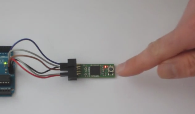
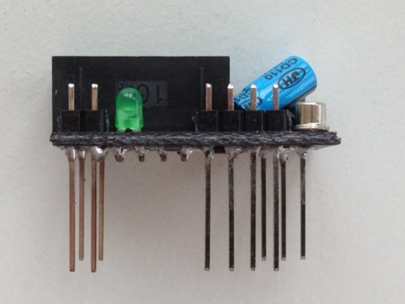
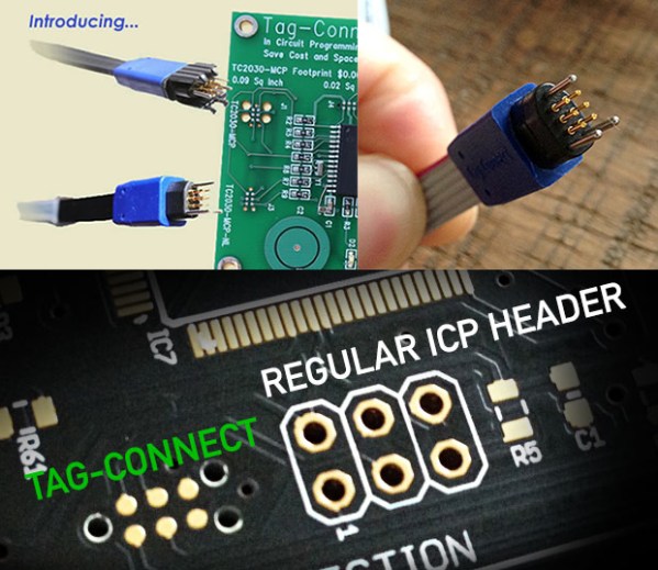
There are so many small embedded development systems, such as the Trinket that still rely on standard headers. Reducing the size of the programming headers and interface headers is an issue that deserves more attention than it currently receives. Based on Tag-Connect, a proprietary connector built around pogo-style pins, your PCB does not actually require any on-board mating connector. The PCB footprint simply has test-pads that connect with the pogo-pins and holes that allow for a rock solid connection. While the Tag-Connect header is a bit expensive (it costs about $34), you only need to buy it once.
It would be great to see even smaller Tag-Connect cables. Do you have a similar solution? What about something even smaller and more compact? Write in to tell us about any ultra-compact connector solutions you have been using!