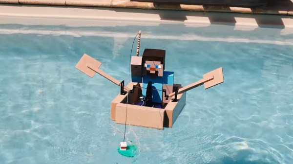
Looking to recreate those relaxing Minecraft fishing sessions in real life, [electrosync] recently set out to 3D print himself a blocky remote controlled boat, complete with a similarly cubic occupant to ride in it. Each element of the build, from the oars to the bobber on the end of the fishing line, has been designed to look as faithful to the source material as possible. In fact, the whole thing is so accurate to the game that it’s almost surreal to see it rowing around the pool.
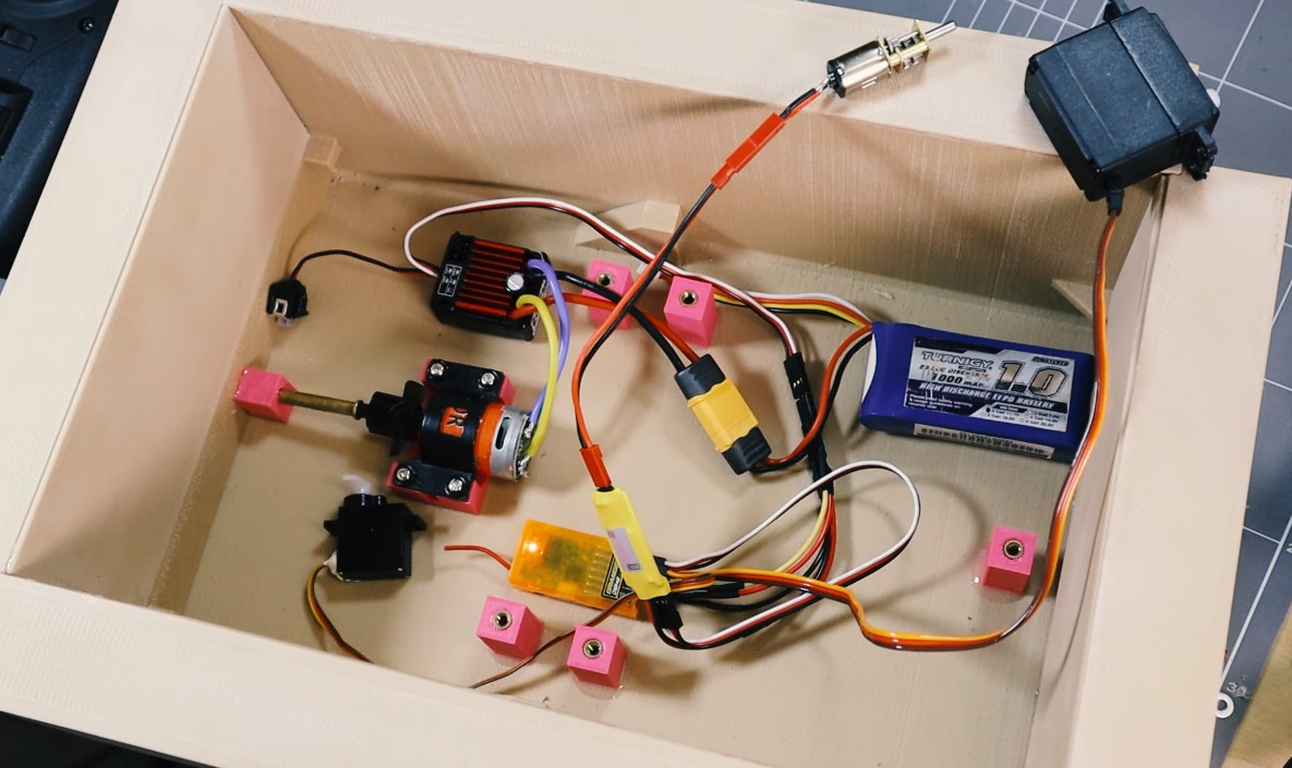
That said, some of the resemblance is only skin deep. For example the rowing action, though it appears to be properly synchronized to the boat’s movement through the water, is completely for show. A standard propeller and rudder arrangement under the boat provide propulsion and directional control, and [electrosync] notes its actually powerful enough to push the boat very near to its scale top speed from the game, despite the exceptionally poor hydrodynamics of what’s essentially just a rectangle.
Speaking of which, [electrosync] even went through the trouble of printing the hull in wood-fill PLA and coating it in polyester resin to make sure it was watertight. Granted he could have just made the boat out of wood in the first place, saving himself the nearly 60 hours it took to print the hull parts, but that would have been cheating.
Beyond the servos and motors that move the boat and the oars, [electrosync] had to give his 3D printed fisherman a considerable amount of dexterity. Servos embedded into the 3D printed parts allow “Steve” to rotate at the hips and raise and lower his arm. With a fishing pole slipped into a hole printed into the hand, he’s able to cast out his magnetic bobber and see whats biting.
We’ve actually seen quite a number of projects that allow virtual objects inside Minecraft to interact with the real world, but comparatively few efforts to recreate objects from the game’s blocky universe, so the change of pace is nice.
Continue reading “RC Minecraft Boat Patrols The Pool For Treasure”