Proprietary Fan Blows, Gets PWM Upgrade

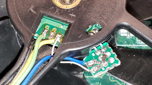
Proprietary components are the bane of anyone who dares to try and repair their own hardware. Nonstandard sizes, lack of labeling or documentation, and unavailable spare parts are all par for the course. [Jason] was unlucky enough to have an older Dell computer with a broken, and proprietary, cooling fan on it and had to make some interesting modifications to replace it.

The original fan had three wires and was controlled thermostatically, meaning that a small thermistor would speed up the the fan as the temperature increased. Of course, the standard way of controlling CPU fans these days is with PWM, so he built a circuit which essentially converts the PWM signal from the motherboard into a phantom thermistor. It’s even more impressive that it was able to be done with little more than a MOSFET and a Zener diode.

Unfortunately, there was a catch. The circuit only works one way, meaning the fan speed doesn’t get reported to the motherboard and the operating system thinks the fan has failed. But [Jason] simply disabled the warning and washed his hands of that problem. If you don’t want to use a CPU fan at all, you can always just dunk your entire computer in mineral oil.

Beat The Streets With This Text Spraying Robot

In the midst of striking for climate change awareness, you may need some extra hands. That’s what [Anred Zynch] thought when they built Strettexter, the text-spraying writing robot that sprays onto streets.

The machine is loaded with 8 spray cans placed into a wooden box (a stop line with a wooden ledge to prevent the cans from falling out) and is fixed on top of a skateboard. It uses a PWN/Servo shield soldered onto an Arduino Uno connected to 8 servo motors (TowerPro SG90s) to control each of the spray bottles. A table converts every character into 5×8 bit fonts to fit the size of the spraying module. The device also includes a safety switch, as well as an encoder for measuring the horizontal distance traveled.

The Strettexter is activated by pulling on the skateboard once it’s been set up and connected to power (for portability, it uses a 8000mAh power bank). In its current configuration, the words stretch out pretty long, but some additional testing will probably lead to better results depending on the constraints of your canvas. The shorter the words, the more difficult it is for the white text to be legible, since there is significant spacing between printed bits.

We don’t condone public vandalism, so use this hack at your own discretion.

Continue reading “Beat The Streets With This Text Spraying Robot”

FM Signal Detection The Pulse-Counting Way

Compared to the simple diode needed to demodulate AM radio signals, the detector circuits used for FM are slightly more complicated. Wrapping your head around phase detectors, ratio detectors, discriminators, and quadrature detectors can be quite an exercise. There’s another demodulation method that’s not so common, but thankfully it’s also pretty easy to understand: the pulse counting detector.

As [Allan (W2AEW)] notes in the video below, pulse counting is a bit of a misnomer. Pulse counting works by generating a narrow, fixed-width square wave pulse at a set point in the received FM signal’s waveform, usually at the zero-crossing point. Since the frequency of the modulated carrier changes, the duty cycle of the resulting pulse train varies. That means there will be a fixed number of pulses, but by taking the average voltage of the pulse train, we can tease out the original audio frequency signal.

Simple in theory is often more complicated in practice, and [W2AEW] goes into some detail about those complications, such as needing to use a down-converter to make the peak-to-peak frequency deviation in the pulse train more easily detectable. As is his style, he walks us through a test circuit to prove that the theory works in practice. A simple two-transistor circuit generates the pulses at the zero-crossing point, a low-pass filter cleans up the signal, and a cheap audio amplifier reproduces the original audio. It’s a crude circuit to be sure, relying on the stray capacitance of the breadboard to work, but it proves the point and serves as a jumping-off point for further experiments – perhaps using an Arduino to count the pulses?

We always enjoy [W2AEW]’s videos and learn a lot from them. Not long ago we featured another of his videos talking about the mysteries of RF modulation; SSB, anyone?

Continue reading “FM Signal Detection The Pulse-Counting Way”

Twelve Channels Of LEDs Give RRRRGGGGBBBB Light

If you’ve ever searched Mouser or Digikey for LEDs parametrically, you won’t find just one red in your LEDs. You won’t find one green. There is quite literally an entire rainbow of colors of LEDs, and this rainbow goes into infrared and ultraviolet. You can search LEDs by frequency, and an RGEB LED is right at your fingertips. The ‘E’ stands for Emerald, and it’s better than a Bayer filter.

[ayjaym] over on Instructables realized anyone could buy a dozen frequencies of high-power LEDs, and the obvious application for this is to turn it into a tunable light source. The Angstrom is twelve LEDs, all different colors, and all controlled by PWM and piped down a single optical fiber. It’s an RRRRGGGGBBBB LED, ideal for microscopy, forensics, colorimetry, and seeing octoreen.

The heart of this device are twelve 3W star LEDs, with the following wavelengths: 390, 410, 440, 460, 500, 520, 560, 580, 590, 630, 660, and 780 nm. That’s deep red to almost ultra violet, and everything inbetween. These are powered by a 5 V, 60 W power supply, and controlled via a Raspberry Pi with 12 PWM channels in a circuit that’s basically just a bunch of MOSFETs. Proper heatsinking is required.

The impressive part of this build is the optics. A 3D printed mount holds and connects optical fibers and sends them into an optical combiner that is basically just a square acrylic rod. This is output to another optical fiber that will shine on just about anything. A webpage running on a Raspberry Pi sets the PWM channels of all the LEDs, and the resulting output shows up at the end of an optical fiber. It’s great if you want to look at something in a specific frequency of light. It also looks really cool, so that’s a bonus.

Get Twelve Charlieplexed PWM Outputs From An ATtiny85

Most of us are aware that charlieplexing can drive a large number of LEDs from a relatively small number of I/O pins, but [David Johnson-Davies] demonstrates adding another dimension to that method to create individually controlled PWM outputs as well. His ATtiny85 has twelve LEDs, each with individually-set brightness levels, and uses only four of the five I/O pins on the device.

Each LED can be assigned a brightness between 0 (fully off) and 63 (fully on). The PWM is done by using one of the timers in the ATtiny85 to generate a periodic interrupt, and the ISR for the interrupt takes care of setting the necessary ratios of on and off times for each charlieplexed output. The result? Twelve flicker-free LEDs with individually addressable brightness levels, using an 8-pin microcontroller and just a few passive components on a tiny breadboard. There’s even one I/O pin left on the ATtiny85, for accepting commands or reading a sensor.

[David] really wrings a lot out of the ATtiny series of microcontrollers with his compact projects, like his Tiny Function Generator (which recently got an update.) He also demonstrated that while charlieplexing is usually used with LEDs, charlieplexing can be used with switches just as easily.

Active Strain Relief For 3D-Printer Filament

Buying 3D-printer filament is little like eating potato chips: you can’t stop at just one. You start with basic black PLA, then you need a particular color for a special project, then you start experimenting with different plastics, and before you know it, you’ve got dozens of reels lined up. Trouble is, unless you move the in-use reel right over the printer, the filament can get a bit unruly as the printer sucks it up. What to do?

How about building an active strain relief system for your filament collection? That what [Daniel Harari] chose to do, and we have to say that it looks pretty slick. The idea is to keep the filament slack before it enters the printer’s extruder no matter where the reel is positioned relative to the printer. The active bit is a little like a low-force extruder, using a couple of pinch rollers from an old 2D-printer to pay out filament when needed. A clever sensor, consisting of a 3D-printed funnel and a copper wire contact loop, detects when the printer has taken up all the slack in the filament and triggers a payout from the feeder. In a nice touch, the feeder motor is controlled by a couple of 555s rather than a microcontroller. The short clip below shows the feeder being triggered and paying out a little more slack.

In the final analysis, this is just another in a long series of filament management projects, from dry-boxes to filament meters to end-of-spool alarms. It may be overkill, but [Daniel] put a lot of thought into it, which we always appreciate.

Continue reading “Active Strain Relief For 3D-Printer Filament”

A Quartet Of Drills Put The Spurs To This Electric Utility Vehicle

Low-slung body style. Four-wheel drive. All electric drivetrain. Turns on a dime. Neck-snapping acceleration. Leather seating surface. Is it the latest offering from Tesla? Nope; it’s a drill-powered electric utility vehicle, and it looks like a blast to drive.

Surprisingly, this isn’t a just-for-kicks kind of build. There’s actually a practical reason for the low form factor and long range of [Axel Borg]’s little vehicle. We’ll leave the back story to the second video below, but suffice it to say that this will be a smaller version of the crawler NASA used to roll rockets out to the launch pad, used instead to transport his insanely dangerous looking manned-multicopter. The running gear on this vehicle is the interesting bit: four hefty electric drills, one for each of the mobility cart wheels. The drills are powered by a large series-connected battery pack putting out 260V at full charge. The universal motors of the drills are fine with DC, and the speed of each is controlled via the PWM signals from a pair of cordless drills. The first video below shows [Axel] putting it through its paces; he didn’t hold back at all, but the vehicle kept coming back for more.

We know this cart is in service to another project, but we’d have a hard time concentrating on anything if we had the potential for that much fun sitting in the shop. Still, we hope that multirotor gets a good test flight soon, and that all goes well with it.

Continue reading “A Quartet Of Drills Put The Spurs To This Electric Utility Vehicle”