If you’ve ever searched Mouser or Digikey for LEDs parametrically, you won’t find just one red in your LEDs. You won’t find one green. There is quite literally an entire rainbow of colors of LEDs, and this rainbow goes into infrared and ultraviolet. You can search LEDs by frequency, and an RGEB LED is right at your fingertips. The ‘E’ stands for Emerald, and it’s better than a Bayer filter.
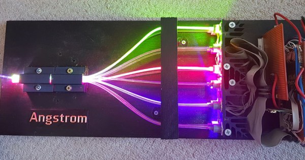
[ayjaym] over on Instructables realized anyone could buy a dozen frequencies of high-power LEDs, and the obvious application for this is to turn it into a tunable light source. The Angstrom is twelve LEDs, all different colors, and all controlled by PWM and piped down a single optical fiber. It’s an RRRRGGGGBBBB LED, ideal for microscopy, forensics, colorimetry, and seeing octoreen.
The heart of this device are twelve 3W star LEDs, with the following wavelengths: 390, 410, 440, 460, 500, 520, 560, 580, 590, 630, 660, and 780 nm. That’s deep red to almost ultra violet, and everything inbetween. These are powered by a 5 V, 60 W power supply, and controlled via a Raspberry Pi with 12 PWM channels in a circuit that’s basically just a bunch of MOSFETs. Proper heatsinking is required.
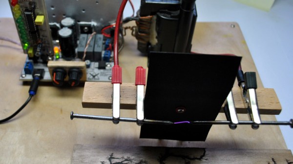
The impressive part of this build is the optics. A 3D printed mount holds and connects optical fibers and sends them into an optical combiner that is basically just a square acrylic rod. This is output to another optical fiber that will shine on just about anything. A webpage running on a Raspberry Pi sets the PWM channels of all the LEDs, and the resulting output shows up at the end of an optical fiber. It’s great if you want to look at something in a specific frequency of light. It also looks really cool, so that’s a bonus.