How many times have you wished for a pocket-sized multimeter? How about a mini microcontroller-based testing rig? Have you ever dared to dream of a device that does both?
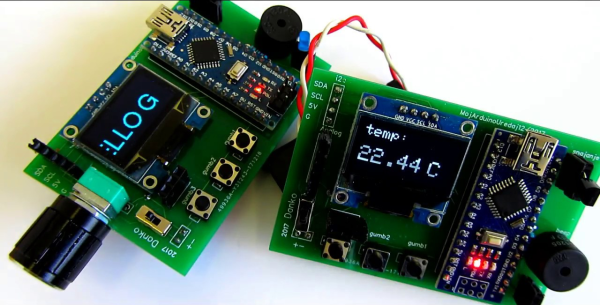
Multiduino turns an Arduino Nano into a Swiss Army knife of portable hacking. It can function as an analog multimeter to measure resistance, voltage drop, and continuity. It can also produce PWM signals, read from sensors, do basic calculator functions, and display the health of its rechargeable battery pack.
Stick a 10kΩ pot in the left-side header and you can play a space shooter game, or make line drawings by twisting the knob like an Etch-A-Sketch. Be sure to check out the detailed walk-through after the break, and a bonus video that shows off Multiduino’s newest functions including temperature sensing, a monophonic music player for sweet chiptunes, and a virtual keyboard for scrolling text on the OLED screen. [Danko] has a few of these for sale in his eBay store. They come assembled, and he ships worldwide. The code for every existing function is available on his site.
You know the saying: “Dogs have people, cats have servants.” This is especially true when your feline overlord loses track of time and insists on being fed at oh-dark-thirty. You’re tempted to stay in bed feigning death, but that’s a tall order with the cat sitting on your chest and staring into your soul.
An automatic cat feeder would be nice at moments like these, but off-the-shelf units are pricey. [Mom Will Be Proud] decided to roll his own cat feeder, and the results are pretty impressive for what amounts to a trash can build. Two old food cans form the body — a Pringles can on top to hold the food and a nut can below for the servo. The metal ends of the cans nest together nicely, and with a large section removed from each, an aperture opens every time the hopper rotates, dropping food down a chute. A BeagleBone Black controls the servo, but anything with PWM outputs should do the trick. We’d lean toward the ESP8266 ecosystem for WiFi support for remotely controlling feedings, and we’d probably beef up the structure with PVC tube to prevent unauthorized access. But it’s a simple concept, and simple is a good place to start.
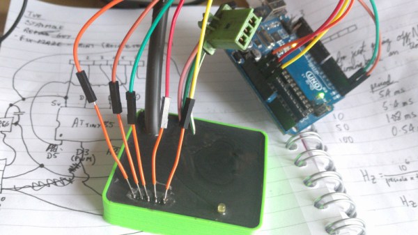
After swapping the engine out in his scooter, [James Stanley] made an unfortunate discovery. The speedometer was digitally controlled, and while the original engine had a sensor which would generate pulses for it to interpret, his new engine didn’t. Learning that the original sensor would pull the signal wire to ground each time it detected a tooth of one of the spinning gears, [James] reasoned he needed to find a way to detect the scooter’s speed and create these pulses manually.
To find the scooter’s speed, he installed a magnet on the front wheel and a hall effect sensor on the fork to detect each time it passed by. Since the wheel is of a known circumference, timing the pulses from the sensor allows calculation of the current speed. A GPS receiver could be used if you wanted fewer wires, but the hall effect sensor on the wheel is simple and reliable. With the speed of the scooter now known, he needed to turn that into a signal the speedometer understands.
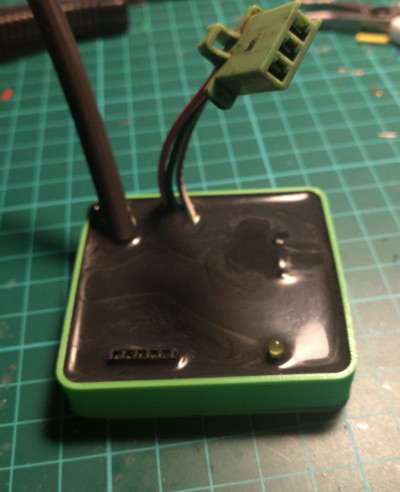
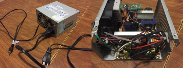
Speedometer controller potted with resin.
[James] wrote a program for an ATmega that would take the input from the wheel sensor and use it to create a PWM signal. This PWM signal drives a transistor, which alternates the speedometer sensor wire between low and floating. With a bit of experimentation, he was able to come up with an algorithm which equated wheel speed to the gearbox speed the speedometer wanted with accuracy close enough for his purposes.
While the software side of this project is interesting in its own right, the hardware is an excellent case study in producing robust electronic devices suitable for use on vehicles. [James] 3D printed a shallow case for the circuit board, and potted the entire device with black polyurethane resin. He even had the forethought to make sure he had a debugging LED and programming connector before he encapsulated everything (which ended up saving the project).
While the specific scenario encountered by [James] is unlikely to befall others, his project is an excellent example of not only interfacing with exiting electronics but producing rugged and professional looking hardware without breaking the bank. Even if scooters aren’t your thing, there are lessons to be learned from this write-up.
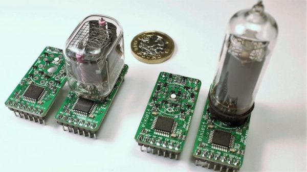
As cool as Nixies are — we’ll admit that to a certain degree, familiarity breeds contempt — they can be tricky to integrate. [dekuNukem] notes that aside from the high voltages, laying hands on vintage driver chips like the 7441 can be challenging and expensive. The problem was solved with about $3 worth of parts, including an STM32 microcontroller and some high-voltage transistors. The PCBs come in two flavors, one for the IN-12 and one for the IN-14, and connections for the SPI interface and both high- and low-voltage supplies are brought out to header pins. That makes the module easy to plug into a motherboard or riser card. The driver supports overdriving to accommodate poisoned cathodes, 127 brightness levels for smooth dimming, and a fully adjustable RBG backlight under the tube. See the boards in action in the video below, which features a nicely styled, high-accuracy clock.
From Nixie tachs to Nixie IoT clocks, [dekuNukem]’s boards should make creative Nixie projects even easier. But if you’re trying to drive a Nixie Darth Vader, you’re probably on your own.
Most projects are built on abstractions. After all, few of us can create our own wire, our own transistors, or our own integrated circuits. A few months ago, [Julian Ilett] found a problem using the Arduino library for PWM. Recently, he revisited the issue and used his own PWM code to fix the problem. You can watch the video below.
Of course, neither the Arduino library nor [Julian’s] code is actually producing PWM. The Atmel CPU’s hardware is doing the work. The Arduino library gives you a wrapper called analogWrite — especially handy if you are not using an Atmel CPU where the same abstraction will do the same work. The issue arose when [Julian] broke the abstraction to invert the PWM output.
Ever wanted to try your hand at wood burning? If you already threw away your first soldering iron—you know the one: plugged straight in to the wall, no temperature control, came with a thick piece of tin foil to rest it on—don’t despair. Pyrography pens don’t cost that much. The variable power supply they plug into, though: that’s another story. Those cost more than they probably should.
The project nearly became Fail of the Week fodder after [td0g] saw huge voltage spikes across the MOSFET. A 47kΩ resistor took care of those, and a heat sink salvaged from the junk bin will prolong the transistor’s life. [td0g] added a push button that cycles through five heat settings, and an LED to show the status. After that, all he had to do was add a male RCA input to connect the pens he already has.
Okay, so you wouldn’t be caught dead dropping money on some fancy power supply for this new hobby. Don’t want to buy pens, either? Roll your own from a plasma arc lighter.
We must all have at some time or another spotted a hack that seems like an incredible idea and which just has to be tried, but turns out to have been stretching the bounds of what is possible just a little too far. A chunk of our time has disappeared without trace, and we sheepishly end up buying the proper part for the job in hand.
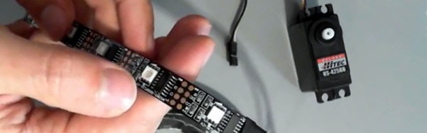
[Orionrobots] had a conversation with a YouTube follower about LED strips. An LED strip contains a length of ready-made PWM drivers, they mused. Wouldn’t it be great then, if each of the drivers on a strip could be connected to a servo, making the strip a ready-made single-stop SPI servo driver. With a large multi-servo robot to build, he set to work on a strip of WS2801s.
If you are in the Soldering Zone and have elite skills at the iron, then soldering a wire to a surface mount driver chip is something entirely possible. For mere mortals though it’s a bit of a challenge, and he notes just how much extra time it’s added to the project. The fun starts though when the servo is hooked up, the best that can be said is that it vibrates a bit. On paper, the LED drivers should be able to drive a servo, because they can create the correct waveform. But in practice the servo is designed to accept a logic level input while the driver is designed to sit in series with an LED and control its current. In practice therefore the voltages required for a logic transition can’t quite be achieved.
He concludes by recommending that viewers splash out on a servo driver board rather than trying an LED strip. We applaud him for the effort, after all it’s a hack any of us might have thought of trying for ourselves.