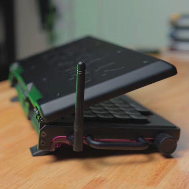
Last time, I showed you how to throw together a few modules and make a working macropad that could act like a keyboard or a mouse. My prototype was very simple, so there wasn’t much to debug. But what happens if you want to do something more complex? In this installment, I’ll show you how to add the obligatory blinking LED and, just to make it interesting, a custom macro key.
There is a way to print data from the keyboard, through the USB port, and into a program that knows how to listen for it. There are a few choices, but the qmk software can do it if you run it with the console argument.
The Plan
In theory, it is fairly easy to just add the console feature to the keyboard.json file:
I recently picked up one of those cheap macropads (and wrote about it, of course). It is surprisingly handy and quite inexpensive. But I felt bad about buying it. Something like that should be easy to build yourself. People build keyboards all the time now, and with a small number of keys, you don’t even have to scan a matrix. Just use an I/O pin per switch.
The macropad had some wacky software on it that, luckily, people have replaced with open-source alternatives. But if I were going to roll my own, it would be smart to use something like QMK, just like a big keyboard. But that made me wonder, how much trouble it would be to set up QMK for a simple project. Spoiler: It was pretty easy.
The Hardware
Simple badge or prototype macropad? Why not both?
Since I just wanted to experiment, I was tempted to jam some switches in a breadboard along with a Raspberry Pi Pico. But then I remembered the “simple badge” project I had up on a nearby shelf. It is simplicity itself: an RP2040-Plus (you could just use a regular Pi Pico) and a small add-on board with a switch “joystick,” four buttons, and a small display. You don’t really need the Plus for this project since, unlike the badge, it doesn’t need a battery. The USB cable will power the device and carry keyboard (or even mouse) commands back to the computer.
Practical? No. But it would be easy enough to wire up any kind of switches you like. I didn’t use the display, so there would be no reason to wire one up if you were trying to make a useful copy of this project.
[Nicholas LaBonte] shows off a Cyberdeck Handheld that demonstrates just how good something can look when care and attention goes into the design and fabrication. He wanted to make something that blended cyberpunk and nautical aesthetics with a compact and elegant design, and we think he absolutely succeeded.
On the inside is a Raspberry Pi and an RTL-SDR. The back of the unit is machined from hardwood, and sports a bronze heat sink for the Raspberry Pi. The front has a prominent red PSP joystick for mouse input and a custom keyboard. The keyboard is especially interesting. On the inside it’s a custom PCB with tactile switches and a ATmega32U4 running QMK firmware — a popular choice for DIY keyboards — and presents to the host as a regular USB HID device.
The keys are on a single plate of little tabs, one for each key, that sits between the front panel and press on the tact switches inside.
How did he make those slick-looking keys? It’s actually a single plate that sits between the front panel and the switches themselves. [Nicholas] used a sheet of polymer with a faux-aluminum look to it and machined it down, leaving metal-looking keys with engraved symbols as tabs in a single panel. It looks really good, although [Nicholas] already has some ideas about improving it.
On the right side is the power button and charging port, and astute readers may spot that the power button is where a double-stack of USB ports would normally be on a Raspberry Pi 5. [Nicholas] removed the physical connectors, saving some space and connecting the USB ports internally to the keyboard and SDR.
As mentioned, [Nicholas] is already full of ideas for improvements. The bronze heat sink isn’t as effective as he’d like, the SDR could use some extra shielding, and the sounds the keyboard ends up making could use some work. Believe it or not, there’s still room to spare inside the unit and he’d maybe like to figure out a way to add a camera, GPS receiver, or maybe a 4G modem. We can’t wait! Get a good look for yourself in the video, embedded below.
Doesn’t this look fantastic? Hard to believe it, but the base of this keyboard began life as a cutting board, and there’s a gallery to prove it. This is actually [androidbrick]’s second foray into this type of upcycling.
This time, [androidbrick] used a FiiO KB3 and replaced the bottom half of the plastic shell with a hand-routed kitchen cutting board. The battery has been disabled and it works only in wired mode, which is fine with me, because then you get to use a curly cord if you want.
Image by [androidbrick] via redditThe switches are mostly Gateron EF Currys, though [androidbrick] left some of the original Gateron G Pro 3.0 on the stabilized keys just for comparison. As you might imagine, the overall sound is much deeper with a wooden bottom. You can check out the sound test on YouTube if you’d like, though it’s pretty quiet, so turn it up.
Those keycaps look even nicer from top-down, which you’ll see in the sound test video linked above. Just search ‘JCM MOA GMK’ on Ali and you’ll find them in a bunch of colorways for around $20. Apparently, [androidbrick] was saving them for months, just waiting for this build.
[Jeremy Weatherford] clearly has a knack for explaining projects well enough for easy reproduction but goes way further than most and has created a four-part YouTube series detailing every step from project inception to the final assembly, covering all aspects of 3D modelling and PCB design for a custom MacroPad design. Many tools are introduced along the way, all of which help reduce complexity and, by extension, the scope for errors. As every beginner hacker knows, early successes breed confidence and make for better and more ambitious projects.
Part 1 covers the project motivation and scope and introduces a keyboard layout editor tool. This tool allows one to take a layout idea and generate a JSON file, which is then used to drive keyboard tools. XYZ to produce a usable KiCAD project. The tool only generates a PCB project and an associated netlist file. No schematic is created; you don’t need one for a simple layout.
A very basic keyboard layout
Part 2 is a walkthrough of the design process in KiCAD, culminating in ordering the PCB from JLCPCB and assembling the surface-mount parts. This particular design uses a controller based on the Sea-Picro RP2040 module, but there are many options if you have other preferences. [Jeremy] shows what’s possible with the selected suppliers, but you need not follow this step precisely if you have other ideas or want to use someone local.
Part 3 covers exporting the mechanical aspects of the PCB out of KiCAD and into a 3D CAD program, specifically OnShape. [Jeremy] covers some crucial details, such as how to read the mechanical drawing of the keys to work out where to place the top plate. It’s very easy to plough straight in at this stage and make a design which cannot be assembled! The plan is to use a simple laser-cut box with a bottom plate with mounting holes lining up with those on the PCB. A Top plate is created by taking the outline of the PCB and adding a little margin. An array of rectangular cutouts are designed for the keys to protrude, lining up perfectly with where the keys would be when mounted on the PCB below. The sides of the case are formed from laser-cut sections that lock into each other and the laser-cut base—using the laser joint feature-script addon tool from the OnShape community channel. A second feature script addon is used to auto-layout the laser-cut components onto a single sheet. A CAM application called Kiri Moto is used to export for laser cutting and is available on the OnShape store.
Touchpads, or trackpads, have been around since the 1980s. Today, you can often find them in laptops and notebook computers as pointing devices. With no moving parts, a trackpad are easy to integrate into the body of a portable computer. they’re much smaller than the traditional mouse. Until the advent of multitouch and gestures over the past two decades, though, they were generally poor substitutes for an actual mouse. These days, trackpads have enough features that some users prefer them even on their desktop computers. If you’re that type of person and don’t want to shell out a big pile of money for an Apple, Logitech, or other off-the-shelf trackpad you can always build your own.
Image by [ambrush] via Hackaday.IOOkay, so this isn’t a traditional keyboard, but you can probably figure out why the RuneRing is here. Because it’s awesome! Now, let me give you the finer points.
Hugely inspired by both ErgO and Somatic, RuneRing is a machine learning-equipped wearable mouse-keyboard that has a configurable, onboard ML database that can be set up to detect any gesture.
Inside the ring is a BMI160 6-axis IMU that sends gesture data to the Seeed Studio nRF52840 mounted on the wrist. Everything is powered with an 80mAh Li-Po lifted from a broken pair of earbuds.
Instead of using a classifier neural network, RuneRing converts IMU data to points in 24-dimensional space. Detecting shapes is done with a statistical check. The result is a fast and highly versatile system that can detect a new shape with as few as five samples.