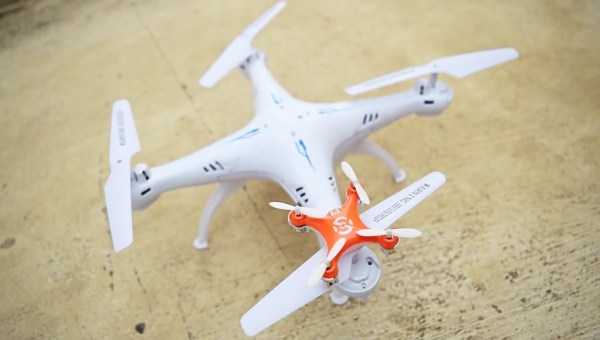
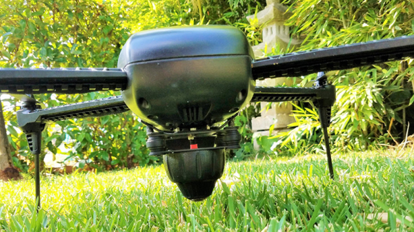
Flying a drone usually leads to–sooner or later–crashing a drone. If you are lucky, you’ll see where it crashes and it won’t be out of reach. If you aren’t lucky, you’ll know where it is, but it will be too high to easily reach. The worst case is when it just falls out of the sky and you aren’t entirely sure where. [Just4funmedia] faced this problem and decided to use some piezo buzzers and an Arduino to solve it.
Yeah, yeah, we know. You don’t really need an Arduino to do this, although it does make it easy to add some flexibility. You can pick two tones that are easy to hear and turn on the buzzers with a spare channel or sense a loss of signal or power.
[prubeš] shows that parts printed with carbon fiber filament are as strong, or at least as stiff, as you’d expect. He then shows that his method for producing carbon fiber parts with a mixture of traditional lay-up and 3D printing is even stronger and lighter.
[prubeš] appears to be into the OpenR/C project and quadcopters. These things require light and strong parts for maximum performance. He managed to get strength with carbon fiber fill filament, but the parts weren’t light enough. Then he saw [RichMac]’s work on Thingiverse. [RichMac] designed parts with pre-planned grooves in which he ran regular carbon fiber tow with epoxy. This produced some incredibly strong parts. There’s a section in his example video, viewable after the break, where he tests a T joint. Even though the plastic starts to fail underneath the carbon fiber, the joint is still strong enough that the aluminum tube inside of it fails first.
[prubeš] innovation on [RichMac]’s method is to remove as much of the plastic from the method as possible. He designs only the connection points of the part, and then designs a 3D printable frame to hold them in place. After he has those in hand, he winds the tow around the parts in a sometimes predetermined path. The epoxy cures onto the 3D print creating a strong mounting location and the woven carbon fiber provides the strength.
His final parts are stronger than 100% infill carbon fill prints, but weighs 8g instead of 12g. For a quadcopter this kind of saving can add up fast.
While studying failure modes for quadcopters, and how to get them safely to the ground with less than a full quad of propellers, a group of researchers at the Institute for Dynamic Systems and Control at ETH Zurich came up with a great idea: a mode of flight that’s like the controlled spinning descent of a maple seed.
The Monospinner runs on the absolute minimum number of moving parts. Namely, one. Even a normal helicopter has a swash plate for adjustable blade pitch, and a tail rotor to keep it from spinning. Give up the idea that you want to keep it from spinning, and you can achieve controlled flight with a lot less. Well, one motor and a whole lot of math and simulation.
The Monospinner is carefully weighted so that it’s as stable as possible while spinning, but so far it’s unable to spin itself up from a standstill. In initial tests, they attached it to a pivot to help. The best part of the video (below) is when the researcher throws it, spinning, into the air and it eventually stabilizes. Very cool.
The mass media are funny in the way they deal with new technology. First it’s all “Wow, that’s Cool!”, then it’s “Ooh, that’s scary”, and finally it’s “BURN THE WITCH!”. Then a year or so later it’s part of normal life and they treat it as such. We’ve seen the same pattern repeated time and time again over the years.
Seasoned readers may remember silly stories in the papers claiming that the Soviets could somehow use the technology in Western 8-bit home computers for nefarious purposes, since then a myriad breathless exclusives have predicted a youth meltdown which never materialised as the inevitable result of computer gaming, and more recently groundless panics have erupted over 3D printing of gun parts. There might be a British flavour to the examples in this piece because that’s where it is being written, but it’s a universal phenomenon wherever in the world technologically clueless journalists are required to fill column inches on technical stories.
The latest piece of technology to feel the heat in this way is the multirotor. Popularly referred to as the drone, you will probably be most familiar with them as model-sized aircraft usually with four rotors. We have been fed a continuous stream of stories involving tales of near-misses between commercial aircraft and drones, and there is a subtext in the air that Something Must Be Done.
Are multirotors unfairly being given bad press? It certainly seems that way as the common thread among all the stories is a complete and utter lack of proof. But before we rush to their defence it’s worth taking a look at the recent stories and examining their credibility. After all if there really are a set of irresponsible owners flying into commercial aircraft then they should rightly be bought to book and it would do us no favours to defend them. So let’s examine each of those incident reports from that BBC story.
Every new generation of computers repeats the techniques used by the earlier generations. [Kim Salmi] created an ASCII-based quadcopter simulation game using an Arduino that displays on the Arduino serial monitor. The modern twist is the controller: an accelerometer supplements the joystick for immersive play. And of course there are flashing LEDs.
An Arduino Uno provides the processing power and drives the serial monitor. A joystick and a Hitachi H48C accelerometer are mounted on a breadboard and wired to the Uno. The tilting of the accelerometer controls the height and left-right motion of the quadcopter on the screen. The joystick sets the the ‘copter in hover mode and lowers a ‘rescue’ line. Another LED warns when the maximum height, the vertical limit of the screen, is reached. The joystick also selects one of the three quadcopters, which have different performance characteristics.
There’s a video after the break. [Kim] provides the source code so you use it as a reference for handling the joystick and accelerometer inputs.
[luca] has always wanted a flying robot, but despite the recent popularity of quadcopters and drones [luca] has never seen a drone that is truly autonomous. Although sometimes billed as autonomous, quadcopters and fixed wing aircraft have always had someone holding a remote, had to stay in a controlled environment, or had some off-board vision system.
Since [luca] is building a coaxial copter – something that looks like a ducted fan with a few vanes at the bottom – there will be control issues. Normal helicopters use the pitch of the blades and the torque produced by the tail rotor to keep flying straight. A quadcopter uses two pairs of motors spinning in opposite directions to stay level. With just two rotors mounted on top of each other, you would think [luca]’s coaxial copter is an intractable problem. Not so; there are bizarre control systems for this type of flying machine that make it as nimble in the sky as any other helicopter.
The design of this flying robot is a bit unlike anything on the market. It looks like a flying ducted fan, with a few electronics strapped to the bottom. It’s big, but also has the minimum number of rotors, to have the highest power density possible with current technology. With a few calculations, [luca] predicted this robot will be able to hoist an IMU, GPS, ultrasonic range finder, optical flow camera, and a LIDAR module in the air for about fifty minutes. That’s a remarkably long flight time for something that hovers, and we can’t wait to see how [luca]’s build turns out.
[Jeremy Cook] has been playing around with strandbeests for a while, but never had one that walked until he put a motor on it and made it R/C controlled.
These remote controlled strandbeests can’t be too heavy or they have trouble moving. He didn’t want to get too complicated, either. [Jeremy] decided his first idea – hacking a cheap R/C car – wouldn’t work. The motors and AA batteries in these cars are just too heavy. Then he realized he had a broken quadcopter lying around. The motors were all burnt out, but the battery, controller, and driver board still works. On a hunch, he hooked up beefier motors to the front and left rotor control, and found that it worked just fine.
The rest of the work was just coupling it to the mechanism. The mechanism is made of wood and metal tubes. [Jeremy] found that the strandmaus had a tendency to fall down. He figures that’s why the original strandbeests had so many legs.
For his next iteration he wants to try to make it more stable, but for now he’s just having fun seeing his little legged contraption scoot around the floor. Video after the break.