It may be hard to believe, but it’s time for the Hackaday Prize again! The 2023 Hackaday Prize was announced last weekend at Hackaday Berlin, and entries are already pouring in. The first-round challenge is all about “Re-engineering Education,” which means you’ve got to come up with a project idea that helps push back the veil of ignorance somehow. Perhaps you’ve got a novel teaching tool in mind, or a way to help students learn remotely. Or maybe your project is aimed at getting students involved and engaged. Whatever it is — and whatever the subject matter; it doesn’t just have to be hacking-adjacent — get an entry together, build a team, and get to work. The first round closes on April 25, so get to it!
radio568 Articles
Two-Tube Spy Transmitter Fits In The Palm Of Your Hand
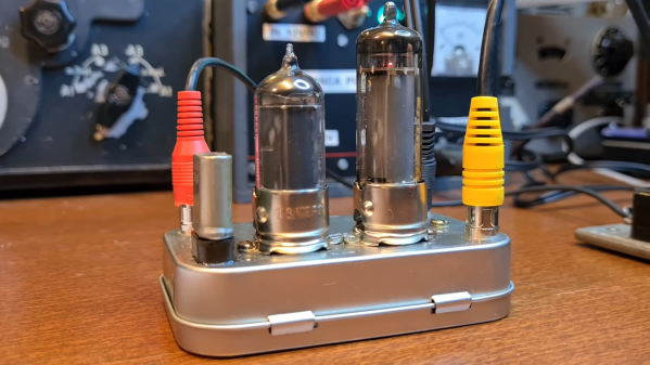
It’s been a long time since vacuum tubes were cutting-edge technology, but that doesn’t mean they don’t show up around here once in a while. And when they do, we like to feature them, because there’s still something charming, nay, romantic about a circuit built around hot glass and metal. To wit, we present this compact two-tube “spy radio” transmitter.
From the look around his shack — which we love, by the way — [Helge Fykse (LA6NCA)] really has a thing for old technology. The typewriter, the rotary phones, the boat-anchor receiver — they all contribute to the retro feel of the space, as well as the circuit he’s working on. The transmitter’s design is about as simple as can be: one tube serves as a crystal-controlled oscillator, while the other tube acts as a power amplifier to boost the output. The tiny transmitter is built into a small metal box, which is stuffed with the resistors, capacitors, and homebrew inductors needed to complete the circuit. Almost every component used has a vintage look; we especially love those color-coded mica caps. Aside from PCB backplane, the only real nod to modernity in the build is the use of 3D printed forms for the coils.
But does it work? Of course it does! The video below shows [Helge] making a contact on the 80-meter band over a distance of 200 or so kilometers with just over a watt of power. The whole project is an excellent demonstration of just how simple radio communications can be, as well as how continuous wave (CW) modulation really optimizes QRP setups like this.
Continue reading “Two-Tube Spy Transmitter Fits In The Palm Of Your Hand”
Hams Watch For Meteors
After passing an exam and obtaining a license, an amateur radio operator will typically pick up a VHF ratio and start talking to other hams in their local community. From there a whole array of paths open up, and some will focus on interesting ways of bouncing signals around the atmosphere. There are all kinds of ways of propagating radio waves and bouncing them off of various reflective objects, such as the Moon, various layers of the ionosphere, or even the auroras, but none are quite as fleeting as bouncing a signal off of a meteor that’s just burned up in the atmosphere.
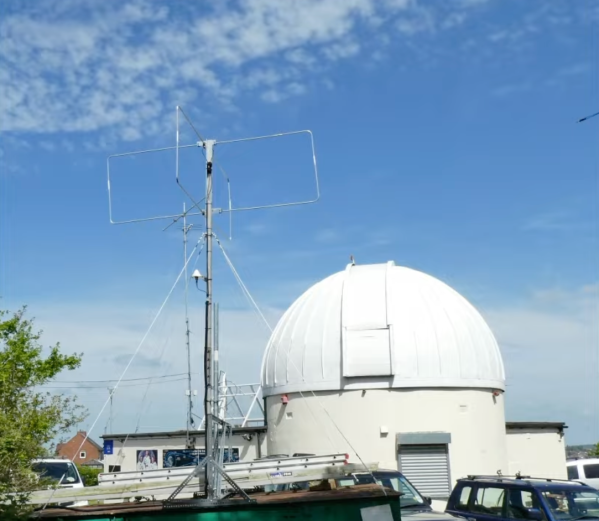
While they aren’t specifically focused on communicating via meteor bounce, The UK Meteor Beacon Project hopes to leverage amateur radio operators and amateur radio astronomers to research more about meteors as they interact with the atmosphere. A large radio beacon, which has already been placed into service, broadcasts a circularly-polarized signal in the six-meter band which is easily reflected back to Earth off of meteors. Specialized receivers can pick up these signals, and are coordinated among a network of other receivers which stream the data they recover over the internet back to a central server.
With this information, the project can determine where the meteor came from, some of the properties of the meteors, and compute their trajectories by listening for the radio echoes the meteors produce. While this is still in the beginning phases and information is relatively scarce, the receivers seem to be able to be built around RTL-SDR modules that we have seen be useful across a wide variety of radio projects for an absolute minimum of cost.
Long-Distance Gaming Over Packet Radio
The amateur radio community often gets stereotyped as a hobby with a minimum age requirement around 70, gatekeeping airwaves from those with less experience or simply ignoring unfamiliar beginners. While there is a small amount of truth to this on some local repeaters or specific frequencies, the spectrum is big enough to easily ignore those types and explore the hobby without worry (provided you are properly licensed). One of the best examples of this we’ve seen recently of esoteric radio use is this method of using packet radio to play a game of Colossal Cave Adventure.
Packet radio is a method by which digital information can be sent out over the air to nodes, which are programmed to receive these transmissions and act on them. Typically this involves something like email or SMS messaging, so playing a text-based game over the air is not too much different than its intended use. For this build, [GlassTTY] aka [G6AML] is using a Kenwood TH-D72 which receives the packets from a Mac computer. It broadcasts these packets to his node, which receives these packets and sends them to a PDP-11 running the game. Information is then sent back to the Kenwood and attached Mac in much the same way as a standard Internet connection.
The unique features of packet radio make it both an interesting and useful niche within the ham radio community, allowing for all kinds of uses where data transmission might otherwise be infeasible or impossible. A common use case is APRS, which is often used on VHF bands to send weather and position information out, but there are plenty of other uses for it as well.
Enormous Metal Sculpture Becomes An Antenna
Those who have worked with high voltage know well enough that anything can be a conductor at high enough voltages. Similarly, amateur radio operators will jump at any chance to turn a random object into an antenna. Flag poles, gutters, and even streams of water can be turned into radiating elements for a transmitter, but the members of this amateur radio club were thinking a little bit bigger when they hooked up their transmitter to this giant sculpture.
For those who haven’t been to the Rochester Institute of Technology (RIT) in upstate New York, the enormous metal behemoth is not a subtle piece of artwork and sits right at the entrance to the university. It’s over 70 feet tall and made out of bronze and steel, a dream for any amateur radio operator. With the university’s permission and some help to ensure everyone’s safety during the operation, the group attached a feedline to the sculpture with a magnet, while the shield wire was attached to a ground rod nearby. A Yaesu FT-991 running on only 5 watts and transmitting in the 20-meter band was able to make contacts throughout much of the eastern United States with this setup.
This project actually started as an in-joke within the radio club, as reported by Reddit user [bbbbbthatsfivebees] who is a member. Eventually the joke became reality, as the sculpture is almost a perfect antenna for certain ham bands. Others in the comments noted that they might have better luck with lower frequency bands such as the 40-meter band or possibly the 60-meter band, due to the height of the structure. And, for those who are still wondering if you really can use a stream of water to transmit radio waves, it is indeed possible.
Review: XHDATA D-219 Short Wave Radio Receiver
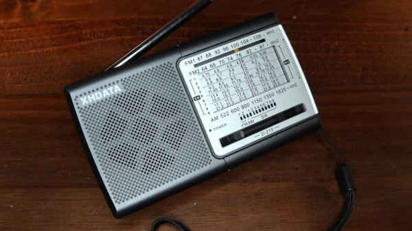
As any radio amateur will tell you, the world of radio abounds with exciting possibilities. Probably the simplest pursuit of them all is that of the SWL, or short wave listener, who scours the airwaves in search of interesting stations. SWLs will often have fully-featured setups with high-end general-coverage communications receivers and tuned antenna arrays, but it can start with the cheapest of radios at its bottom end. Such a radio is the subject of this review, the XHDATA D-219 is a miniature portable receiver that costs under ten dollars, yet is currently the talk of the town in SWL circles. This interest is in no small amount due to its being an especially low-price way to get your hands on a shortwave radio using one of the SIlicon Labs integrated software-defind radio receiver chips. We don’t often review a consumer radio here at Hackaday, but with an avid eye for unexpected gems at the cheaper end of the market this one’s worth a second look.
What Do You Get For Your Tenner?
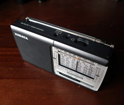
I ordered my D-219 from the XHDATA website, spending about £10 including the postage from China. The usual wait ensued before the package landed on my doormat, and inside was the radio in its box with an instruction leaflet. It’s a small unit about 135 mm x 75 mm x 30 mm, and it follows closely the form factor of other similar radios.
On the top is the extensible antenna with an on-off switch and sockets for headphone and 5 V power, on the side are side-on knobs for tuning and volume, while on the front is the speaker and old-style multi-band tuning display.
On the back is a flip-up stand and a hatch for a pair of AA cells. There’s a band switch covering AM, nine different shortwave bands from 4.75 MHz to 22 MHz, the east Asian FM band from 64 MHz to 87 MHz, and the international FM band from 87 MHz to 108 MHz. The tuning indicator is very old-school, a vertical bar that moves across a frequency scale with the tuning knob. Continue reading “Review: XHDATA D-219 Short Wave Radio Receiver”
Building A Communications Grid With LoRaType
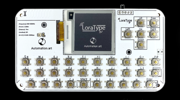
Almost all of modern society is built around various infrastructure, whether that’s for electricity, water and sewer, transportation, or even communication. These vast networks aren’t immune from failure though, and at least as far as communication goes, plenty will reach for a radio of some sort to communicate when Internet or phone services are lacking. It turns out that certain LoRa devices are excellent for local communication as well, and this system known as LoraType looks to create off-grid text-based communications networks wherever they might be needed.
The project is based around the ESP32 platform with an E22 LoRa module built-in to allow it to operate within its UHF bands. It also includes a USB-based battery charger for its small battery, an e-paper display module to display the text messages without consuming too much power, and a keyboard layout for quickly typing messages. The device firmware lets it be largely automated; it will seek out other devices on the local mesh network automatically and the user can immediately begin communicating with other devices on that network as soon as it connects.
There are a few other upsides of using a device like this. Since it doesn’t require any existing communications infrastructure to function, it can be used wherever there are no other easy options, such as in the wilderness, during civil unrest where the common infrastructure has been shut down, or simply for local groups which do not have access to cell networks or Internet. LoRa is a powerful tool for these use cases, and it’s even possible to network together larger base stations to extend the range of devices like these.


