Exploring The Early Days Of QRP Radio

Morse code might seem obsolete but for situations with extremely limited bandwidth it’s often still the best communications option available. The code requires a fair amount of training to use effectively, though, and even proficient radio operators tend to send only around 20 words per minute. As a result of the reduced throughput, a type of language evolved around Morse code which, like any language, has evolved and changed over time. QRP initially meant something akin to “you are overloading my receiver, please reduce transmitter power” but now means “operating radios at extremely low power levels”. [MIKROWAVE1] explores some of the earlier options for QRP radios in this video.

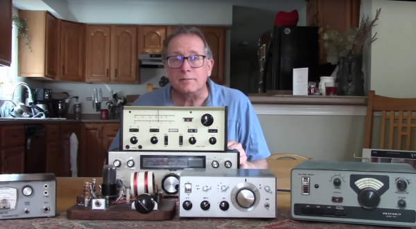
There’s been some debate in the amateur radio community over the years over what power level constitutes a QRP operation, but it’s almost certainly somewhere below 100 watts, and while the radios in this video have varying power levels, they tend to be far below this upper threshold, with some operating on 1 watt or less. There are a few commercial offerings demonstrated here, produced from the 70s to the mid-80s, but a few are made from kits as well. Kits tended to be both accessible and easily repairable, with Heathkit being the more recognizable option among this category. To operate Morse code (or “continuous wave” as hams would call it) only requires a single transistor which is why kits were so popular, but there are a few other examples in this video with quite a few more transistors than that. In fact, there are all kinds of radios featured here with plenty of features we might even consider modern by today’s standards; at least when Morse code is concerned.

QRP radios in general are attractive because they tend to be smaller, simpler, and more affordable. Making QRP contacts over great distances also increases one’s ham radio street cred, especially when using Morse, although this benefit is more intangible. There’s a large trend going on in the radio world right now surrounding operating from parks and mountain peaks, which means QRP is often the only way to get that done especially when operating on battery power. Modern QRP radios often support digital and voice modes as well and can have surprisingly high prices, but taking some cues from this video about radios built in decades past could get you on the radio for a minimum or parts and cost, provided you can put in the time.

Continue reading “Exploring The Early Days Of QRP Radio”

LoRa Goes To The Moon

LoRa is a communications method that allows for long range radio contacts to be made using typically low-powered devices. This shouldn’t be surprising given that LoRa is short for “long range” which typically involves distances on the order of a few kilometers. However, a group of students are taking the “long range” moniker to the extreme by attempting to send and receive a signal with a total path of around 768,000 kilometers by using some specialized equipment to bounce a LoRa signal off of the moon and receive it back on Earth.

Earth-Moon-Earth (EME) communications are typically done by amateur radio operators as a hobby, since the development of communications satellites largely rendered other uses of this communication pathway obsolete. A directional antenna and a signal typically on the order of 1 kW are often used to compensate for the extremely high path losses. Using LoRa, which makes use of chirp spread spectrum modulation, they hope to reduce this power requirement significantly. The signals are being generated and received on a set of HackRF One devices fed into a series of amplifiers, and the team is also employing a set of large dish antennas, one in New Jersey and another in Alaska, to send and receive the messages.

The software used is the open-source SDRAngel which is useful for controlling the HackRF and moving the LoRa signal up to 1296 MHz. Normally LoRa is operated on an unlicensed band, but this method allows for finer control of not only frequency but also bandwidth, which helps reduce the impacts of path loss. Right now they have not yet completed their contacts with the Alaska station (partially due to that antenna being covered in snow) but we hope to hear more news in the future. In the meantime, take a look at some more traditional long-range communications using this protocol with more manageable-sized antennas.

Image courtesy of NASA, Public domain, via Wikimedia Commons

Building A Receiver With The ProgRock2 Programmable Crystal

Crystals are key to a lot of radio designs. They act as a stable frequency source and ensure you’re listening to (or transmitting on) exactly the right bit of the radio spectrum. [Q26] decided to use the ProgRock2 “programmable crystal” to build a receiver that could tune multiple frequencies without the usual traditional tuning circuitry. 

 The ProgRock2 is designed as a tiny PCB that can be dropped into a circuit to replace a traditional crystal. The oscillators onboard are programmable from 3.5KHz to 200 MHz, and can be GPS discliplined for accuracy. It’s programmable over a micro USB pot, and can be set to output 24 different frequencies, in eight banks of three. When a bank is selected, the three frequencies will be output on the Clock0, Clock1, and Clock2 pins.There was some confusion regarding the bank selection on the ProgRock2. It’s done by binary, with eight banks selected by grounding the BANK0, BANK1, and BANK2 pins. For example, grounding BANK2 and BANK0 would activate bank 5 (as 101 in binary equals 5). Once this was figured out, [Q26] was on top of things.

In his design, [Q26] hooked up the ProgRock2 into his receiver in place of the regular crystal. Frequency selection is performed by flipping three switches to select banks 0 to 7. It’s an easy way to flip between different frequencies accurately, and is of particular use for situations where you might only listen on a limited selection of amateur channels.

For precision use, we can definitely see the value of a “programmable crystal” oscillator like this. We’ve looked at the fate of some major crystal manufacturers before, too. Video after the break.

Continue reading “Building A Receiver With The ProgRock2 Programmable Crystal”

The Cheap And Available Microwave Playground

There’s something of a mystique about RF construction at the higher frequencies, it’s seen as a Black Art only practiced by elite wizards. In fact, UHF and microwave RF circuitry is surprisingly simple and easy to understand, and given the ready availability of low-noise block downconverters (LNBs) for satellite TV reception there’s even a handy source of devices to experiment on. It’s a subject on which [Polprog] has brought together a handy guide.

A modern LNB has some logic for selecting one of a pair of local oscillators and to use vertical or horizontal polarization, but remains otherwise a very simple device. There’s an oscillator, a mixer, and an RF amplifier, each of which uses microwave transistors that can with a little care be repurposed. The page demonstrates a simple transmitter, but it’s possible to create more powerful  devices by using the amplifier stage “in reverse”.

Meanwhile the oscillator can be moved by loading the dielectric resonators with PVC sleeving, and the stripline filters can even be modified with a fine eye for soldering and some thin wire. Keep an eye out in thrift stores and yard sales for old satellite dishes, and you can give it a go yourself. It’s a modern equivalent of the UHF tuner hacking enjoyed by a previous generation.

Half Crystal Radio, Half Regenerative Radio

A rite of passage in decades past for the electronics experimenter was the crystal radio. Using very few components and a long wire antenna, such a radio could pick up AM stations with no batteries needed, something important in the days when a zinc-carbon cell cost a lot of pocket money. The days of AM broadcasting may be on the wane, but it’s still possible to make a crystal set that will resolve stations on the FM band. [Andrea Console] has done just that, with a VHF crystal set that whose circuit also doubles as a regenerative receiver when power is applied.

The key to a VHF crystal set lies in the highest quality tuned circuit components to achieve that elusive “Q” factor. In this radio that is coupled to a small-signal zero voltage threshold FET that acts as a detector when no power is applied, and the active component in a regenerative radio when it has power. The regenerative radio increases sensitivity and selectivity by operating at almost the point of oscillation, resulting in a surprisingly good receiver for so few parts. Everyone should make a regenerative radio receiver once in their life!

Tiny Three-Tube Receiver Completes Spy Radio Suite

In our surface-mount age, it’s easy to be jaded about miniaturization. We pretty much expect every circuit to be dimensionally optimized, something that’s easy to do when SMDs that rival grains of sand are available. But dial the calendar back half a century or so and miniaturization was a much more challenging proposition.

Challenging, perhaps, but by no means unachievable, as [Helge Fyske (LA6NCA)] demonstrates with this ultra-compact regenerative vacuum tube receiver. It’s a companion to his recent “spy transmitter,” a two-tube radio built in — or on, really — an Altoids tin. The transmitter was actually a pretty simple circuit, just a crystal-controlled oscillator and an RF amplifier really, but still managed about 1.5 Watts output on the 80-meter ham band.

The receiver circuit ended up being much more complicated, as receivers do, and therefore harder to cram into the allotted space. [Helge]’s used a three-tube regenerative design, with one tube each devoted to the RF amp, detector/mixer, and audio amplifier stages. As in the transmitter, the receiver tubes are mounted on the outside of the box, with the inside crammed full of components. [Helge] had to be quite careful about component positioning, to prevent interstage coupling and other undesirable side effects of building in such close quarters.

Was it worth it? Judging by the video below, absolutely! We’ve rarely heard performance like that from even a modern receiver with all the bells and whistles, let alone from a homebrew design under such constraints. It sounds fantastic, and hats off to [Helge] for completing his spy radio suite in style.

Continue reading “Tiny Three-Tube Receiver Completes Spy Radio Suite”

Your Multimeter Might Be Lying To You

Multimeters are indispensable tools when working on electronics. It’s almost impossible to build any but the most basic of circuits without one to test and troubleshoot potential issues, and they make possible a large array of measurement capabilities that are not easily performed otherwise. But when things start getting a little more complex it’s important to know their limitations, specifically around what they will tell you about circuits designed for high frequency. [watersstanton] explains in this video while troubleshooting an antenna circuit for ham radio.

The issue that often confuses people new to radio or other high-frequency projects revolves around the continuity testing function found on most multimeters. While useful for testing wiring and making sure connections are solid, they typically only test using DC. When applying AC to the same circuits, inductors start to offer higher impedance and capacitors lower impedance, up to the point that they become open and short circuits respectively. The same happens to transformers, but can also most antennas which often look like short circuits to ground at DC but can offer just enough impedance at their designed frequency to efficiently resonate and send out radio waves.

This can give some confusing readings, such as when testing to make sure that a RF connector isn’t shorted out after soldering it to a coaxial cable for example. If an antenna is connected to the other side, it’s possible a meter will show a short at DC which might indicate a flaw in the soldering of the connector if the user isn’t mindful of this high-frequency impedance. We actually featured a unique antenna design recently that’s built entirely on a PCB that would show this DC short but behaves surprisingly well when sending out WiFi signals.

Continue reading “Your Multimeter Might Be Lying To You”