A Dreamcast VMU With A Secret

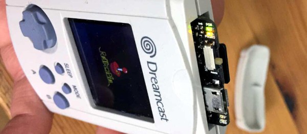
Since the Raspberry Pi range of boards first appeared back in 2012, we’ve seen them cleverly integrated into a host of inventive form factors. Today we bring you the latest offering in this space, [Kite]’s Raspberry Pi Zero W installed in the case of a Sega Dreamcast VMU. The result is a particularly nicely executed build in which the Pi with a few of its more bulky components removed or replaced with low-profile alternatives sits on the opposite side of a custom PCB from a small LCD display.

The PCB contains the relevant buttons, audio, and power supply circuitry, and when installed in a VMU shell makes for a truly professional quality tiny handheld console. In a particularly nice touch the Pi’s USB connectivity is brought out alongside the SD card on the end of the Zero, under the cap that would have originally protected the VMU’s connector. Some minimal paring away of Sega plastic was required but the case is surprisingly unmodified, and there is plenty of space for a decent-sized battery.

The VMU, or Visual Memory Unit, makes an interesting choice for an enclosure, because it is a relic of one of console gaming’s dead ends. It was the memory card for Sega’s last foray into the console market, the Dreamcast, and unlike those of its competitors it formed a tiny handheld console in its own right. Small games for the VMU platform were bundled with full titles, and there was a simple multiplayer  system in which VMUs could be linked together. Sadly the Dreamcast lost the console war of the late 1990s and early 2000s to Sony’s PlayStation 2, but it remains a console of note.

VMUs are not the most common of gaming survivors, but we’ve shown you one or two projects using them. There was an iPod conversion back in 2010, and much more recently some mind-blowing reverse engineering and emulation on the original VMU hardware.

Thanks [Giles Burgess] for the tip.

An Unconference Badge That’s Never Gonna Give You Up

When your publication is about to hold a major event on your side of the world, and there will be a bring-a-hack, you abruptly realise that you have to do just that. Bring a hack. With the Hackaday London Unconference in the works this was the problem I faced, and I’d run out of time to put together an amazing PCB with beautiful artwork and software-driven functionality to amuse and delight other attendees. It was time to come up with something that would gain me a few Brownie points while remaining within the time I had at my disposal alongside my Hackaday work.

Since I am a radio enthusiast at heart, I came up with the idea of a badge that the curious would identify as an FM transmitter before tuning a portable radio to the frequency on its display and listening to what it was sending. The joke would be of course that they would end up listening to a chiptune version of [Rick Astley]’s “Never gonna give you up”, so yes, it was going to be a radio Rickroll.

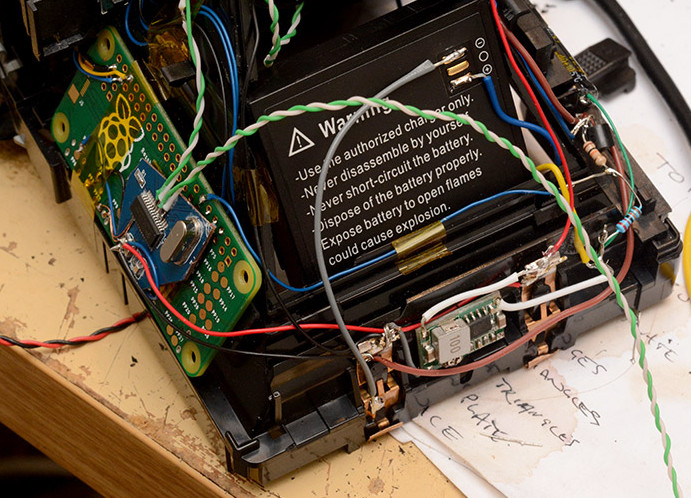
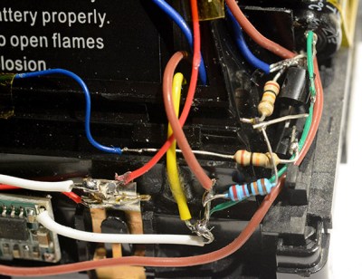
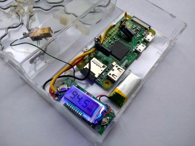
The badge internals.

I evaluated a few options, and ended up with a Raspberry Pi Zero as an MP3 player through its PWM lines, feeding through a simple RC low-pass filter into a commercial super-low-power FM transmitter module of the type you can legally use with an iPod or similar to listen on a car radio. To give it a little bit of individuality I gave the module an antenna, a fractal design made from a quarter wavelength of galvanised fence wire with a cut-off pin from a broken British mains plug as a terminal. The whole I enclosed in a surplus 8mm video cassette case with holes Dremmeled for cables, with the FM module using its own little cell and the Pi powered from a mobile phone booster battery clipped to its back. This probably gave me a transmitted field strength above what it should have been, but the power of those modules is so low that I am guessing the sin against the radio spectrum must have been minor.

At the event, a lot of people were intrigued by the badge, and a few of them were even Rickrolled by it. But for me the most interesting aspect lay not in the badge itself but in its components. First I looked at making a PCB with MP3 and radio chips, but decided against it when the budget edged towards £20 ($27). Then I looked at a Raspberry Pi running PiFM as an all-in-one solution with a little display HAT, but yet again ran out of budget. An MP3 module, Arduino clone, and display similarly became too expensive. Displays, surprisingly, are dear. So my cheapest option became a consumer FM module at £2.50 ($3.37) which already had an LCD display, and a little £5 ($6.74) computer running Linux that was far more powerful than the job in hand demanded. These economics would have been markedly different had I been manufacturing a million badges, but made a mockery of the notion that the simplest MCU and MP3 module would also be the cheapest.

Rickrolling never gets old, it seems, but evidently it has. Its heyday in Hackaday projects like this prank IR repeater seems to have been in 2012.

Nerf Gun Ammo Counter And Range Finder

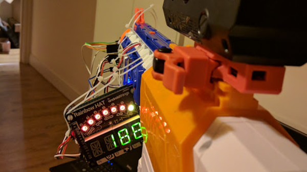
The proliferation of breakout boards that the DIY electronics movement has allowed has been staggering. Buy a few different boards, wire them together to a microcontroller or credit-card computer (both on their own breakout board) and write a bit of code, and you can create some really interesting things. Take Reddit user [Lord_of_Bone]’s Nerf Gun ammo counter and range finder, for example, a great example of having a great idea and looking around for the ways to implement it.

For the range finder, [Lord_of_Bone] looked to an ultrasonic rangefinder. For the ammo counter, [Lord_of_Bone] chose a proximity sensor. To run everything, the Raspberry Pi Zero was used and the visuals were supplied by a Rainbow Hat. The range finder is self-explanatory. The proximity sensor is located at the end of the gun’s muzzle and when it detects a Nerf dart passing by it reduces the ammo count by one. Blu-tack is used to hold everything in place, but [Lord_of_Bone] plans to use Sugru when he’s past the prototype stage.

The one problem [Lord_of_Bone] has with the build is that there’s no way to tell how many Nerf bullets are in the magazine. Currently the wielder must push a button when reloading to reset the count to a preset amount. We’re sure that [Lord_of_Bone] would appreciate any suggestions the Hack-A-Day crowd could offer.

[Lord_of_Bone] gives a full bill of materials, Python code, a lot of pictures and step-by-step instructions so that you, too, can determine how far away your target is, and whether or not you have enough ammo to hit them. We have quite a few Nerf mods on the site, and [Lord_of_Bone] could take a look at this article about how to keep track of your Nerf ammo, and here’s a different method of determining if a Nerf dart has been fired (and measuring its speed.)

[via Reddit] Continue reading “Nerf Gun Ammo Counter And Range Finder”

Finishing A Mini PS One: SLA Vs Extruded

One of the biggest lessons learned by first time 3D printer users is that not everything can be replicated and a printer is a machine and not a miracle worker. It has limitations in terms of what it can print as well as the quality of the output. For teeny tiny objects, the 0.8 mm nozzle will just not do and with resin printers on the rise, the question is, ‘are extruder printers obsolete?’

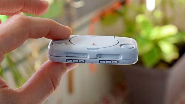
[Dorison Hugo] has made a mini version of the PS One using a Raspberry Pi which you can play games one. The kicker is that in his video, he does a comparison of an SLA printer and a cheaper extruder one for his enclosure. He goes through a laundry-list of steps to print, file, fill, repair, sand paint, sand, paint etc to try to get a good model replica of the original PS One. He then proceeds to print one with an SLA printer and finishes it to compare with the first model. The decals are printed on an inkjet for those who are wondering, and there is a custom cut heatsink in there as well that was salvaged from an old PC.

Spoiler alert! The SLA wins but in our view, just slightly. The idea is that with enough elbow grease and patience, you can get pretty close to making mini models with a cheaper machine. The SLA print needs work too but it is relatively less and for detailed models, it is a much better choice. We really enjoyed watching the process from start to finish including the Dremel work, since it is something that is forgotten when we see a 3D print. Creating something of beauty takes time and effort which stems from a passion to make.

Take a look at the video below of the time lapse and for  SLA printer fans, have a look at the DIY SLA printer which is a Hackaday Prize Entry this year. Continue reading “Finishing A Mini PS One: SLA Vs Extruded”

Hackaday Prize Entry: FabDoc Is Version Control For Project Images

FabDoc is an interesting concept that attempts to tackle a problem many of us didn’t realize we had. There are plenty of version control systems for software, but many projects also have a hardware element or assembly process. Those physical elements need to be documented, but that process does not easily fit the tools that make software development and collaboration easier. [Kevin Cheng] sums FabDoc up as “a system to capture time-lapse pictures as pre-commits.”

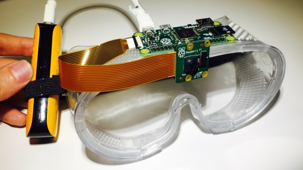
With FabDoc a camera automatically records the physical development process, allowing the developer to focus on work and review later. The images from the camera are treated as pre-commits. Upon review, the developer selects relevant key images (ignoring dead ends or false starts) and commits them. It’s a version control and commit system for the physical part of the development process. The goal is to remove the burden of stopping the work process in order to take pictures, automatically record the development process and attach it to a specific project, and allow easy management of which images to commit.

The current system uses a Raspberry Pi Zero with a camera mounted on safety glasses, and some support software. Some thought has certainly gone into making the system as easy to use and manage as possible; after setting up a repository, scanning a QR code takes care of telling the system what to do and where to put it. The goal is to make FabDoc fast and easy to use so that it can simply work unattended.

We saw a visual twist on version control some time ago with a visual diff for PCBs, which was a great idea to represent changes between PCB designs visually, diff-style. It’s always exciting to see someone take a shot at improving processes that are easy to take for granted.

Add A Second SD Card To The Pi Zero

The Raspberry Pi Zero is a beautiful piece of hardware, fitting an entire Linux computer into a package the size of a pack of gum (don’t chew it, though). However, this size comes with limited IO options, which can be a complication for some projects. In this case, [Hugatry] wanted extra storage, and devised a smart method to add a second SD card to the Pi Zero.

The problem with the Pi Zero is that with only a single USB port, it’s difficult to add any other storage to the device without making things bulkier with hubs or other work arounds. Additionally, the main SD card can’t be removed while the Pi is running, so it makes sense to add an easy-to-use removable storage option to the Pi Zero.

It’s quite a simple hack – all that’s required to pull it off is a few resistors, an SD card connector, and some jumper wires. With everything hooked up, a small configuration change enables the operating system to recognise the new card.

Overall it’s great to see hacks that add further functionality to an already great platform. If you find it’s not powerful enough, you can always try overclocking one. 

Continue reading “Add A Second SD Card To The Pi Zero”

Building A K9 Toy

[James West] has a young Doctor Who fan in the house and wanted to build something that could be played with without worrying about it being bumped and scratched. So, instead of creating a replica, [James] built a simple remote controlled K9 toy for his young fan.

K9 was a companion of the fourth Doctor (played by Tom Baker) in the classic Doctor Who series. He also appeared in several spin-offs. A robotic dog with the infinite knowledge of the TARDIS at hand, as well as a laser, K9 became a favorite among Who fans, especially younger children. [James] wanted his version of K9 to be able to be controlled by a remote control and be able to play sounds from the TV show.

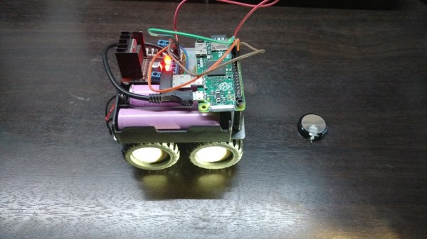
Using some hand-cut acrylic, [James] built K9’s body, then started on plans for the motion control and brains. [James] selected the Raspberry Pi Zero for the controller board, a Speaker pHat for the audio, a couple of motors to move K9 around, and a motor controller. K9 is controlled by a WiiMote and has a button on his back to start pairing with the WiiMote (K9 answers with “Affirmative” when the pairing is successful.) When it came to the head, [James] was a little overwhelmed by trying to make the head in acrylic, so he got some foam board and used that instead. A red LED in the head lights up through translucent red acrylic.

It’s a great little project and [James] has put the Python code up on Github for anyone interested. We’ve had a couple of robot dog projects on the site over the years, like this one and this one.

Continue reading “Building A K9 Toy”