The Raspberry Pi Model B+ was just released, and now everyone who picks one of those up has a few more GPIO pins to play around with. For the millions of people with the two-year-old version of the Pi, we’re still stuck with the same old, same old: 17 GPIOs on the big header, and that’s about it as far as toggling pins goes.
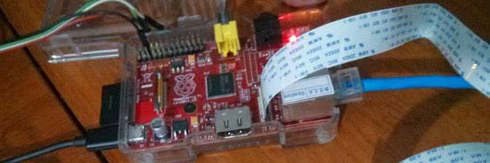
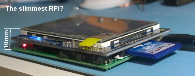
The Broadcom SoC on the Pi has far more GPIO pins than are broken out on the large header, and a few of those go to the CSI camera interface. These GPIOs can be broken out with a few flat cables (Portuguese, Google Translatrix), giving you four more GPIOs, and this technique can also be used with the new, expanded Model B+.
The CSI camera connector has two I²C lines that go directly to the camera, controllable in Linux as GPIO0 and GPIO1. There are two more GPIO connectors on the CSI connector controllable as GPIO5 and GPIO21. By carefully slicing and soldering wires to a flat cable, these GPIO lines can be broken out onto a breadboard.
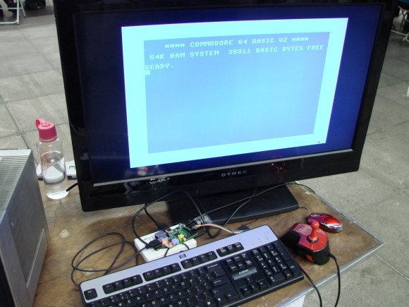
There’s a video below demonstrating these GPIO lines being used to control a few LEDs. Of course, anything that is possible with a normal Raspi GPIO is possible with the CSI connector GPIO lines.
Continue reading “Adding GPIOs To The Raspberry Pi With The Camera Interface”


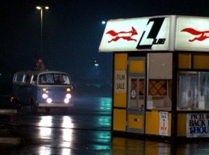 I ran into a guy at Maker Faire Kansas City who I used to scoop ice cream with twenty years ago. We were slinging frozen dairy at a Baskin Robbins in a dying suburban strip mall that had a one-hour photo booth in the parking lot. It was just far enough away from our doorstep that dotting its backside with the hard-frozen ice cream balls that had been scooped and then not always accidentally dropped into the depths of the freezer was challenging. This guy, [Blake], kept a hockey stick hidden in the back room especially for this purpose. I never could get them to fly that far, but he was pretty good at it.