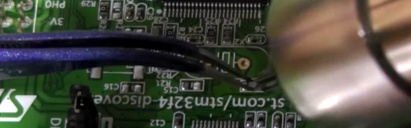
Microcontroller Dev Boards have the main hardware choices already made for you so you can jump right into the prototyping by adding peripherals and writing code. Some of the time they have everything you need, other times you can find your own workarounds, but did you ever try just swapping out components to suit? [Andy Brown] documented his process of transplanting the clock crystal on an STM32F4 Discovery board.
Even if you don’t need to do this for yourself, the rework process he documented in the clip after the break is fun to watch. He starts by cleaning the through-hole joints of the crystal oscillator with isopropyl alcohol and then applies some flux paste to each. From there the rest is all hot air. The crystal nearly falls out due to gravity but at the end he needs to pluck it out with his fingers. We’re happy to see others using this “method” as we always feel like it’s a kludge when we do it. Next he grabs the load caps with a pair of tweezers after the briefest of time under the heat.
We’d like to have a little bit of insight on the parts he replaces and we’re hoping there are a few crystal oscillator experts who can leave a comment below. [Andy] calculates a pair of 30pf load caps for this crystal. We understand the math but he mentions a common value for board and uC input capacitance:
assuming the commonly quoted CP + CI = 6pF
So we asked and [Andy] was kind enough to share his background on the topic:
It’s a general “rule of thumb” for FR4 that the stray capacitance due to the traces on the board and the input (lead) capacitance of the the MCU is in in the range of 4-8pF. I’m used to quoting the two separately (CP,CI) but if you look around you’ll see that most people will combine the two and call it just “CP” and quote a value somewhere between 4 and 8pF. It’s all very “finger in the air” and for general purpose MCU clocks you can get away picking the mid-value and be done with it.
That leaves just one other question; the original discovery board had an in-line resistor on one of the crystal traces which he replaces with a zero ohm jumper. Is it common to include a resistor and what is the purpose for it?
Continue reading “Swapping Dev Board Crystals To Suit Your Needs”
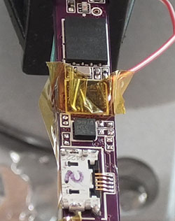 The NoteOn smartpen
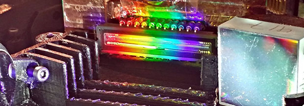
 [Mario], the guy behind OpenExposer, the combination SLA printer, PCB exposer, and laser harp is chugging right along.
  Goliath, the gas-powered quadcopter, had a few problems earlier this month. During its first hover test