No matter what the job at hand is, if you’re going to tackle it, you’re going to need the right kit of tools. And if your job includes making sense out of any of the signals in the virtual soup of RF energy we all live in, then you’re going to need something like the FISSURE RF framework.
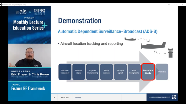
Exactly what FISSURE is is pretty clear from its acronym, which stands for Frequency Independent SDR-Based Signal Understanding and Reverse Engineering. This is all pretty new — it looks like [Chris Poore] presented a talk at DEFCON a few weeks back about using FISSURE to analyze powerline communications between semi-trucks and their trailers, and they’ve got a talk scheduled for next month’s GNU Radio Conference as well. We’ve been looking through all the material we can find on FISSURE, and it appears to be an RF hacker’s dream come true. They’ve got a few examples on Twitter, like brute-forcing an old garage door opener with a security code set by a ten-position DIP switch, and sending tire pressure monitoring system (TPMS) signals to a car. They also mention some of the framework’s capabilities on the GitHub README; we’re especially interested in packet crafting for various protocols. The video below has some more examples of what FISSURE can do.
It looks like FISSURE could be a lot of fun, and very handy for your RF analysis and reverse engineering work. If you’ve been using Universal Radio Hacker like we have, this looks similar, only more so. We’ll be downloading it soon and giving it a try, so be on the lookout for a hands-on report.
Continue reading “Introducing FISSURE: A Toolbox For The RF Hacker”