The guy behind the Microslice, a tiny Arduino-controlled laser cutter, has a new Kickstarter out. It’s called the Multibox PC, and it’s exactly what you need if you want to turn a Raspi, Banana Pi, HummingBoard, or Odroid U3 into an all-in-one desktop. 14″ 1366 x 768 LCD, and speakers turns dev boards into a respectable little Linux box.
If you’re learning to design schematics and lay out PCBs, you should really, really think about using KiCAD. It’s the future. However, Eagle is still popular and has many more tutorials. Here’s another. [Mushfiq] put together a series of tutorials for creating a library, designing a schematic, and doing the layout.
Another kickstarter wristwatch. But wait, this thing has a circular display. That’s really cool. It’s a 1.4″ 220×220 pixel, 262k color display. No, the display doesn’t use a polar coordinate system.
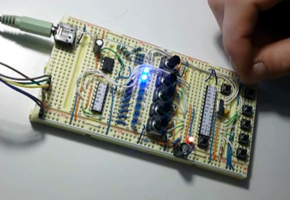
[Jari] wrote a digital logic simulator, Atanua, started selling licenses, and figured out it wasn’t worth developing on his own anymore. As promised, Atanua is now open source. If you want to look at the finances behind Atanua, here you go.
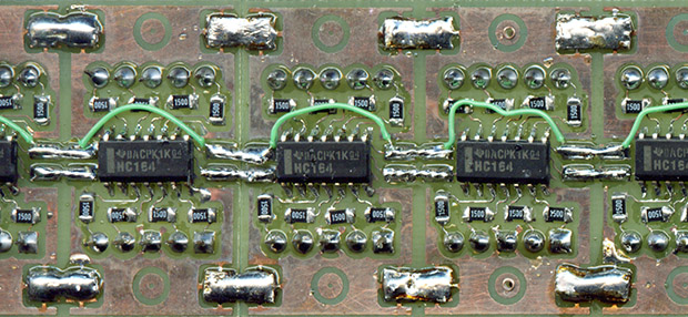
In 1970, you didn’t have a lot of options when it came to memory. One of the best options was Intel’s 1405 shift register – 512 bits of storage. Yes, shift registers as memory. [Ken Shirriff] got his hands on a memory board from a Datapoint 2200 terminal. Each of the display boards had 32 of these shift registers. Here’s what they look like on the inside
There’s a lot of talk about North Korean hackers, and a quick review of the yearly WordPress stats for Hackaday puts a tear in our eye. This year, there were fifty-four views from the Democratic People’s Republic of Korea. That’s just great. It’s awesome to see the hacker ethos make it to far-flung lands and through highly restricted firewalls. There’s still a long road ahead of us, though, and we’ll redouble our efforts on bringing the hacker mindset to Tuvalu and Saint Helena in the year 2015.