3D Printering: Making A Thing With Solidworks, Part I

printering1

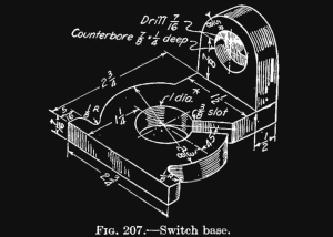
Brian has graciously allowed me to hop on the 3D Printering bandwagon to write a brief intro to the wonderful world of Solidworks. We’ll be making the same ‘thing’ as done in the previous ‘Making a Thing’ tutorials:
engineeringdrawingblack1

Admittedly, most Hackaday readers probably don’t have Solidworks as it is a very expensive program. The main reason we are posting this tutorial is so that you can understand the work flow and compare it to some of the free/open packages out there.

Continue reading “3D Printering: Making A Thing With Solidworks, Part I”

Printing An Aston Martin DB4

CAR

With 3D printers finding their way into the workshops of makers the world over, it was bound to happen sooner or later. [Ivan Sentch] is making an Aston Martin DB4 with a 3D printer.

Before we board the hype train, let’s go over what this is project is not: [Ivan] isn’t making any metal parts with his 3D printer, and the chassis and engine will be taken from a donor car. Also, the printed plastic parts won’t actually make their way into the final build; the 3D printed body panels will be used to pull the final panels in fiberglass. That being said, it’s still an impressive undertaking that’s going to cost [Ivan] $2250 NZD in plastic alone.

[Ivan]’s body panels are made by taking a DB4 model in Solidworks, slicing it up into 105mm squares, giving each square extruded sides, and finally securing them to the wooden form after the parts are printed. There’s still an awful lot of work to be done once the 3D printed parts are all glued together, but it’s still an amazingly impressive – and cheap – way to create a replica of a very famous automobile.

Quadruped Walks Of Four Legs, Rolls On Four Treads

tracked-quadruped-robot

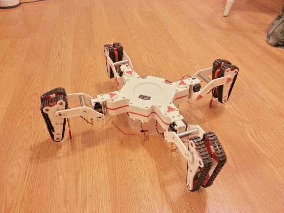
This robot doesn’t know if it’s a walker or a tank. It’s the brain-child of [Marc Hamende] who works as a mechanical engineer by day and mad roboticist at night. The best place to find full details is by digging into the long thread he’s been posting to for about six weeks. It will give you a pretty good snapshot of his approach, starting with SolidWorks renderings of the project, and adding in assembled components as he brings the project together.

The mechanism for each foot is fascinating. He milled the white pieces which stack together to encapsulate the motor that runs the treads. These assemblies pivot to bring the metal rod serving as a walking foot in contact with the ground. But they also make it possible to adjust the treads to deal with rough terrain. A Propeller chip drives the device, with an Xbee module to communicate with the controller.

Don’t miss the video after the break. You’ll hear some skidding as it makes turns, but [Marc] plans to add code to adjust motor speed in order to compensate for the inside/outside differential issues. He’s also posted an image album over at Flickr.

Continue reading “Quadruped Walks Of Four Legs, Rolls On Four Treads”

Olin College Penny Press

Olin Penny Press

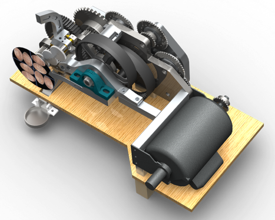
Inspired by souvenir penny presses, [Robert] built the Olin College penny press. This machine stamps out coins with the school’s name and a variety of other patterns. He built it as part of a mechanical structures course, with the goal of designing something that used large forces.

Crushing a penny takes about five tons of force. To deliver that force, [Robert] used a 1 horsepower motor coupled to a custom 1190:1 reduction drive train, which consisted of sprockets, gears, and chains. The aluminium frame supporting the drive train also had to be designed to withstand large forces.

This required of a lot of custom parts, which were made using a CNC mill, a water jet cutter and a mill. All of the CAD drawings are available for anyone who wants to replicate the design.

This beast of a machine weighs about 90 pounds and can squish 12 pennies every minute. Olin College installed the penny press on their campus for anyone to use for free.

Carabiner Helps You Hone Your Milling Skills

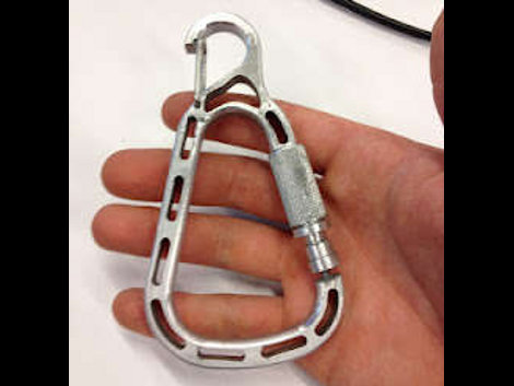
[Christian] is learning to use the metal milling tools at what we assume is his local Hackerspace. We love this about the communal spaces, they provide so many opportunities to delve into new fields. He embarked on a voyage that included visits to most of the machinery in the shop as he build his own carabiner with a magnetic gate. He’s not going to be hanging off the side of a mountain from it. But his keys or a water bottle will find a happy home thanks to the device.

It all started with some sketches to establish the shape of the overall design. From there he spent some time modelling the frame of the carabiner in CAD. He’s lucky enough to have access to a water jet which took the SolidWorks files and cut out the aluminum frame for him. That left a part with very sharp edges, so he used a wood router with a carbide bit to round them over.

The next part is adding the gate. He used an end-mill to add a mounting area on the frame. The locking ring for the gate was textured using a knurling tool, and the rest is milled with a simple cutting tool. This gate uses a magnet to center itself, with the knurled ring as the only mechanical latching mechanism. [Christian] does a good job of demonstrating the completed carabiner in the clip after the break.

Continue reading “Carabiner Helps You Hone Your Milling Skills”

A Pick And Place Machine For Under $1k

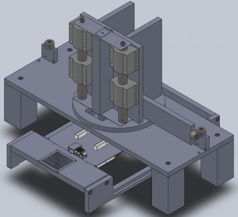
Pick and place machines are marvels of modern technology. They the can lift, orient, align and drop tiny electronic components onto a circuit board that is headed for the reflow oven. On an industrial scale they move so fast it’s a blur in front of your eyes, and they use imaging to ensure proper placement. But that kind of specialized equipment is going to cost a real bundle of money. [Bootstrap] is working on a design that will still be feature-rich, but will allow you to purchase your own pick-and-place machine for under $1000.

The design calls for a two-headed beast. One head is a vacuum tweezers which is capable of moving the parts. The other is a digital microscope that is used for precise positioning. The two heads pivot in and out of place, but it’s the table which holds the PCB that is responsible for positioning the parts. Although there’s nothing built yet, the depth of information that [Bootstrap] published in his post is impressive. He’d like your help making sure there’s no errors in the design before he builds the first three prototypes. If you’re a Solidworks guru he’ll even send you the files upon request.

We’ve seen a couple of different pick and place machines lately so take another look if you missed them the first time.

[via Adafruit]

Marble Machines Roundup

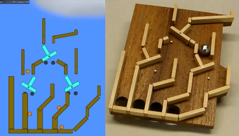
[Denha’s] been building marble machines for years and decided to look a back on some of his favorite marble-based builds  (translated). There’s a slew of them, as well as some thoughts about each. Our favorite part is the digital simulations of the projects. For instance, the image above shows a flip-flop marble machine that was built in a physics simulator. This makes it a lot easier to plan for the physical build as it will tell you exact dimensions before you cut your first piece of material. Both of these images were pulled from videos which can be seen after the break. But this isn’t the most hard-core of pre-build planning. SolidWorks, a CAD suite that is most often used to design 3D models for precision machining, has also been used to model the more intricate machines.

Continue reading “Marble Machines Roundup”