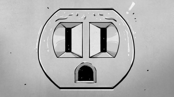
Right now, if you happen to be in Noth America, chances are pretty good that there’s at least one little face staring at you. Look around and you’ll spy it, probably about 15 inches up from the floor on a nearby wall. It’s the ubiquitous wall outlet, with three holes arranged in a way that can’t help but stimulate the facial recognition firmware of our mammalian brain.
No matter where you go you’ll find those outlets and similar ones, all engineered for specific tasks. But why do they look the way they do? And what’s going on electrically and mechanically behind that familiar plastic face? It’s a topic we’ve touched on before with Jenny List’s take on international mains standards. Now it’s time to take a look inside the common North American wall socket, and how it got that way.
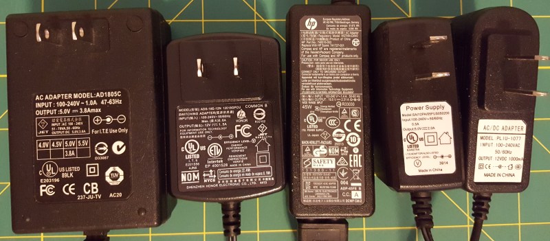
Look on the back of your laptop charger and you’ll find a mess of symbols and numbers. We’d bet you’ve looked at them before and gleaned little or no understanding from what they’re telling you.
These symbols are as complicated as the label on the tag of your shirt that have never taught you anything about doing laundry. They’re the marks of standardization and bureaucracy, and dozens of countries basking in the glow of money made from issuing certificates.
The switching power supply is the foundation of many household electronics — obviously not just laptops — and thus they’re a necessity worldwide. If you can make a power supply that’s certified in most countries, your market is enormous and you only have to make a single device, possibly with an interchangeable AC cord for different plug types. And of course, symbols that have meaning in just about any jurisdiction.
In short, these symbols tell you everything important about your power supply. Here’s what they mean.
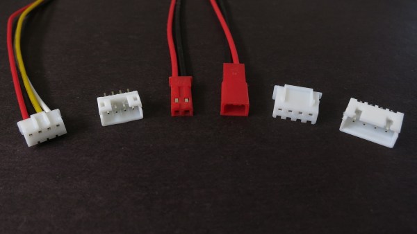
When reading about cool projects and products, it’s common to see wiring plugs labelled “JST connector.” This looks fine until we start getting hands-on and begin hacking things together. Inevitably we find the JST connector from one part fails to fit in the JST connector of another. This is the moment we learn “JST” is not a connector specification. It is short for Japan Solderless Terminals Manufacturing Company, Ltd. A company whose history goes back to 1957 and their website (styled in 1999) lists hundreds of different types.
We can simplify to “JST connector” when chit-chatting about projects. But when it comes to actual hardware specification, that’s not good enough. Which JST connector?
Within the last few years, a lot of companies have started with the aim to disrupt the educational electronics industry using their LEGO-compatible sets. Now they’re ubiquitous, and fighting each other for their slice of space in your child’s box of bricks. What’s going on here?
Raison D’Être
The main reason for LEGO-compatibility is familiarity. Parents and children get LEGO. They have used it. They already have a bunch. When it comes to leveling up and learning about electronics, it makes sense to do that by adding on to a thing they already know and understand, and it means they can continue to play with and get more use from their existing sets. The parent choosing between something that’s LEGO-compatible and a completely separate ecosystem like littleBits (or Capsela) sees having to set aside all the LEGO and buy all new plastic parts and learn the new ecosystem, which is a significant re-investment. littleBits eventually caught on and started offering adapter plates, and that fact demonstrates how much demand there is to stick with the studs.
When designing a piece of hardware that has even the faintest chance of being exposed to the elements, it’s best to repeat this mantra: water finds a way. No matter how much you try to shield a project from rain, splashing, or even just humid air, if you haven’t taken precautions to seal your enclosure, I’ll bet you find evidence of water when you open it up. Water always wins, and while that might not be a death knell for your project, it’s probably not going to help. And water isn’t the only problem that outdoor or rough-service installations face. Particle intrusion can be a real killer too, especially in an environment where dust can be conductive.
There’s plenty you can do to prevent uninvited liquid or particulate guests to your outdoor party, but it tends to be easier to prevent the problem at design time than to fix it after the hardware is fielded. So to help you with your design, here’s a quick rundown of some standards for protection of enclosures from unwanted ingress.
The International Electrotechnical Commission (IEC) is an international body that issues standards on a wide range of electronics-related topics. How wide? Their mandate seems to span rules for household product safety to the specification of safety logic assemblies in nuclear power plants. Want to know how to electrically measure sound loudness? Test methods for digital door lock systems? Or maybe you’re interested in safety interlock systems for laser processing machines. There’s an IEC standard for that too.
Unfortunately, this information is kept behind a paywall. OK, it’s a lot more like a pay fortress. They really, really don’t want you accessing their documents without first coughing up. This is a shame.
The IEC doesn’t just make the standards in a vacuum, however. Before the scribes touch their chisels to the stone tablets, there are draft versions of the standards that are open for public comment by those knowledgeable in the field. And by “those knowledgeable”, we mean you, dear hacker. Head on over to the public commenting page, sign up, and you’ve got free access to every document that’s currently up for discussion.
Now, it does look like the IEC doesn’t want you sharing these PDFs around — they watermark them with your username and threaten all sorts of things if you use them for anything other than commenting purposes — so don’t go abusing the system. But on the other hand, if you are a private individual who knows a thing or two about a thing or two, we think you’re entirely right to look over their shoulders. Let us know in the comments if you find any gems.
They’ve even got a weekly update feature (in the registration pages) that’ll keep you up to date. And who knows, maybe your two cents, submitted to your country’s chapter of the IEC, will influence future international standards.
Wouldn’t it be great if there were just one standard for attaching to, programming, and debugging hardware? If you could just plug in and everything would just work? Dream on, dreamer! But of course we hobbyists aren’t the only people to suffer from multiple standards. Industry has the same problems, writ large. In response to the proliferation of smart devices — microcontrollers, sensors, and their friends — on any given PCB makes it difficult to test them all, much less their function as a system.
The Joint Test Action Group (JTAG) got together in the mid-80s to make automated testing of circuit boards a standardized process. A JTAG port can be found on almost any piece of consumer electronics with enough brains to warrant it, and it’s also a tremendously useful entry point for debugging your own work and hacking into other’s. You’re going to need to use JTAG someday.
Implemented right, it’s a very cool system that lets you test any compliant IC on the board all from a single connector. It’s mostly used by hackers for its ability to run and halt individual processors, and put them in debugging modes, inspecting their memory states, etc. Essentially every microcontroller responds to JTAG commands, and it’s an incredibly widespread and powerful standard. A victory for rationality and standardization!
The connector pinout was, of course, left up to the manufacturer. The horror!
Five Signals
In principle, JTAG uses five signal lines. They form a chain starting at the debugger, where one device’s output is the next device’s input, until the result is returned back to the debugger.
Test Data In (TDI) is the input from the debugger
Test Data Out (TDO) is the return end of the chain
Test Clock (TCK) clocks this data along synchronously, similarly to SPI
Test Mode Select (TMS) lets the devices know that they’re being debugged — it’s a global chip select
Test Reset (TRST) is an optional signal that resets all devices in the chain