[Chris’s] bedroom has a unique setup with an air conditioning unit perched on the wall next to the top of the blinds that cover his window. Normally, to open the blinds he had to tug on a cord and operating the AC meant fiddling with a remote control. Not anymore. Now [Chris] has an all-in-one Raspberry Pi-based solution to drive both.
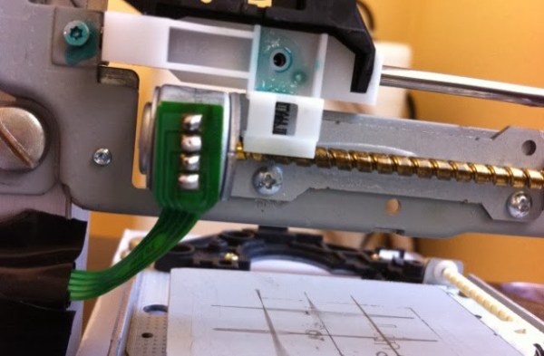
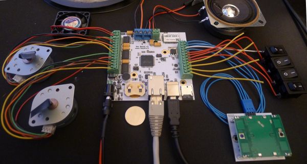
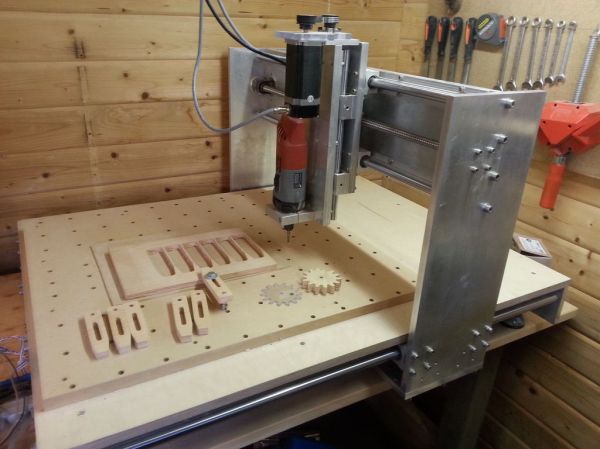
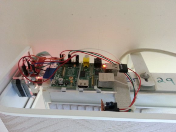
The build uses a stepper motor salvaged from a printer to directly drive the blinds, with a familiar-looking Easy Driver connecting it to the Pi. The motor spins the blinds’ mechanism either open or closed, though at a modest pace that’s slow enough to provide the needed torque. [Chris] added an IR diode plugged into the Pi that imitates the air conditioning unit’s remote control, and simply pointed it directly at the unit’s receiver. An inexpensive WiFi dongle gets the Pi onto the network, allowing [Chris] to interact via a custom web interface. The interface itself not only provides a couple of clickable buttons, but a cleverly-designed status image indicating the position of the blinds.
Make sure you see the video below for a demonstration and for more details on the build. This is one of the better examples of home automation devices we’ve seen recently, especially considering it actually fits the “autonomous” implications discussed in our Ask Hackaday post from a few months back—although a relatively simple automation, [Chris’s] interface does allow for operating both the blinds and the AC on a preselected schedule.