Breakers for the system on a DIN rail, with markings like 48V and 24V and 12V and so on on the bottom, and two hefty devices of some kind on the bottom, probably MPTT controllers, with hefty wires running from them.

Low-Voltage DC Network Build Incited By Solar Panels

Nowadays, some people in Europe worry about energy prices climbing, and even if all the related problems disappear overnight, we’ll no doubt be seeing some amounts of price increase. As a hacker, you’re in a good position to evaluate the energy consuming devices at your home, and maybe even do something about them. Well, [Peter] put some solar panels on his roof, but couldn’t quite figure out a decent way to legally tie them into the public grid or at least his flat’s 220V network. Naturally, a good solution was to create an independent low-voltage DC network in parallel and put a bunch of devices on it instead!

He went with 48V, since it’s a voltage that’s high enough to be efficient, easy to get equipment like DC-DCs for, safe when it comes to legal matters concerned, and overall compatible with his solar panel setup. Since then, he’s been putting devices like laptops, chargers and lamps onto the DC rail instead of having them be plugged in, and his home infrastructure, which includes a rack full of Raspberry Pi boards, has been quite content running 24/7 from the 48V rail. There’s a backup PSU from regular AC in case of overcast weather, and in case of grid power failures, two hefty LiFePO4 accumulators will run all the 48V-connected appliances for up to two and a half days.

The setup has produced and consumed 115kWh within the first two months – a hefty contribution to a hacker’s energy independence project, and there’s enough specifics in the blog post for all your inspiration needs. This project is a reminder that low-voltage DC network projects are a decent choice on a local scale – we’ve seen quite viable proof-of-concept projects done at hackercamps, but you can just build a small DC UPS if you’re only looking to dip your feet in. Perhaps, soon we’ll figure out a wall socket for such networks, too.

A small circuit board glowing purple inset with computer code

Power Cycling Museum Computers On The Cheap

Flicking a circuit breaker to power cycle hundreds of desktop computers inside interactive museum exhibits is hardly ideal. Computers tend to get cranky when improperly shutdown, and there’s an non-zero risk of data loss. However, financial concerns ruled out commercial computer management solutions, and manually shutting down each exhibit at the end of the day is not practical. Tasked with finding a solution, [Jeff Glass] mixed off-the-shelf UPS (uninterruptible power supply) hardware, a Featherwing and some Python to give the museum’s computer-run exhibits a fighting chance.

Without drastically changing the one-touch end-of-day procedure, the only way to properly shutdown the hundreds of computers embedded in the museum exhibits involved using several UPS units, keeping the PCs briefly powered on after the mains power was cut. This in itself solves nothing – while the UPS can trigger a safe shutdown via USB, this signal could only be received by a single PC. These are off-the-shelf consumer grade units, and were never intended to safely shut down more than one computer at a time. However, each 300 watt UPS unit is very capable of powering multiple computers, the only limitation is the shutdown signal and the single USB connection.

To get around this, the Windows task scheduling service was setup to be triggered by the UPS shutdown signal, which itself then triggered a custom Python script. This script then relays the shutdown signal from the UPS to every other computer in the museum, before shutting itself down for the evening.

While many computers can be enabled to boot on power loss, the UPS and safe shutdown scripts meant that this wasn’t an option. To get around this, an ESP32 Featherwing and a little bit if CircuitPython code sends out WOL (wake-on-LAN) signals over Ethernet automatically on power up. This unit is powered by a non-UPS backed power outlet, meaning that it only sends the WOL signal in the morning when mains power is restored via the circuit breaker.

There are undoubtedly a variety of alternative solutions that appear ‘better’ on paper, but these may gloss over the potential costs and disruption to a multi-acre museum. Working within the constraints of reality means that the less obvious fix often ends up being the right one. How would you have tackled this problem? Sound off in the comments below. And while you’re here, make sure to check out our coverage of other UPS solutions, like this supercap UPS.

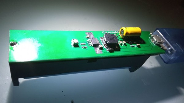
The powerbank PCB, with all the components on one side, 18650 holder on the other, a MicroUSB cable plugged into the PCB's MicroUSB socket

Open Hardware 5V UPS Improves On Cheap Powerbank Design

Often, we need to power a 5V-craving project of ours on the go. So did [Burgduino], and, unhappy with solutions available, designed their own 5V UPS! It takes a cheap powerbank design and augments it with a few parts vital for its UPS purposes.

You might be tempted to reach for a powerbank when facing such a problem, but most of them have a fatal flaw, and you can’t easily tell a flawed one apart from a functioning one before you buy it. This flaw is lack of load sharing – ability to continue powering the output when a charger is inserted. Most store-bought powerbanks just shut the output off, which precludes a project running 24/7 without powering it down, and can cause adverse consequences when something like a Raspberry Pi is involved.

Understandably, [Burgduino] wasn’t okay with that. Their UPS is based on the TP5400, a combined LiIon charging and boost chip, used a lot in simple powerbanks, but not capable of load sharing. For that, an extra LM66100 chip – an “ideal diode” controller is used. You might scoff at it being a Texas Instruments part, but it does seem to be widely available and only a tad more expensive than the TP5400 itself! The design is open hardware, with PCB files available on EasyEDA and the BOM clearly laid out for easy LCSC ordering.

We the hackers might struggle to keep our portable Pi projects powered, employing supercapacitors and modifying badly designed Chinese boards. However, once we find a proper toolkit for our purposes, battery-powered projects tend to open new frontiers – you might even go beyond your Pi and upgrade your router with an UPS addon! Of course, it’s not always smooth sailing, and sometimes seemingly portability-friendly devices can surprise you with their design quirks.

DC UPS Keeps The Internet Up

We occasionally get annoyed that so much gear takes the ubiquitous “wall wart” these days. But one advantage is that the devices operate on DC voltage. [TechRally] takes advantage of this to create an automatic DC UPS with dual outputs to power a router and modem in the event of a power outage. You can see two videos about the project below.

Some may say it would be better to use conventional UPS, but think about it. That UPS has a battery in it that gets converted to AC so the wall wart can convert it back to DC. Each conversion loses some energy, of course, and in the case of a cheap wall wart, you may even lose quite a bit.

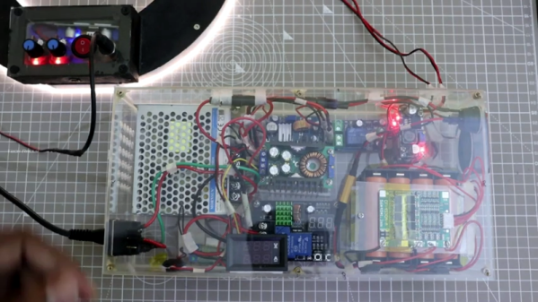
The project contains eight 18650 batteries, an off-the-shelf charge controller, and power converters. Could you do a more efficient custom design? Maybe, but the use of these inexpensive and commonly available modules makes it quick and easy to pull something like this together.

No one would mistake this UPS for a commercial unit, but it does have a certain hacker aesthetic. We wouldn’t carry it through an airport, though. With those digital displays and all the wiring, it looks like a bad TV show’s bomb prop.

If you don’t care about the automatic switchover, we hear that 5V will power a lot of equipment these days and that makes battery operation as simple as stripping a USB cable. This could probably drive some other gear like a connected Raspberry Pi. Or, you could do that job with some supercaps.

Continue reading “DC UPS Keeps The Internet Up”

A Raspberry Pi 400 UPS Add-On, It’s Not All Plain Sailing

Since the recent launch of the all-in-one Raspberry Pi 400, the global hardware community have taken to the new platform and are investigating its potential for hardware enhancements. On the back it has the same 40-pin expansion connector as its single-board siblings, but it’s horizontal rather than vertical, which means that all of the conventional HATs sit in a rather ungainly upright position.

One of the first Pi 400 HATs we’ve seen comes from [Patrick Van Oosterwijck], who has made a very neat 18650-based UPS add-on that is intended to eventually fit in the back of the machine in a similar way to the home computer cartridge peripherals of old. Unfortunately not all has gone according to plan, and in finding out why that is the case we learn something about the design of the 400, and maybe even take a chance to reflect on the Pi Foundation itself.

On the face of it the 400’s interface is the same as that of its single board computer stablemates, but something this project reveals is that its 5 V pins have a current limit of 1 A. This turns out to preclude the type of plug-in Pi UPS that sits on a HAT that we’re used to, in that 1 A through the 5 V pin is no longer enough to run the computer.

This effectively puts a stop to [Patrick]’s project, though he can repurpose it for a Pi 4 and its siblings once he’s dealt with a converter chip overheating problem. He does however make a complaint about the Pi Foundation’s slowness in releasing such data about their products, and given that long-time Pi-watchers will remember a few other blips in the supply of Pi hardware data he has a point. A quick check of the Raspberry Pi GitHub repository reveals nothing related to the Pi 400 at the time of writing, and though it shares much with its Pi 4 sibling it’s obvious that there are enough differences to warrant some extra information.

Hardware hackers may not be part of the core education focus of the Pi range, but a healthy, interested, and active hardware community that feels nurtured by its manufacturer remains key to the supply of interesting Pi-related products feeding into that market. We’d like to urge the Pi Foundation to never forget the hardware side of their ecosystem, and make hardware specification an integral part of every product launch on day one.

If the Pi 400 catches your interest, you can read our review here.

A Super UPS For The Pi

One of the problems with using a Raspberry Pi or most other systems in a production environment is dealing with sudden shutdowns due to power loss. Modern operating systems often keep data in memory that should be on disk, and a sudden power cycle can create problems. One answer is an uninterruptible power supply, but maintaining batteries is no fun. [Scott] wanted to do better, so he built a UPS using supercapacitors.

A supercapacitor UPS is nearly ideal. The caps charge quickly and don’t wear out as a battery does. The capacitors also don’t care if they stay in storage for a long time. The only real downside is they don’t have the capacity that batteries can have, but for a small computer like a Pi Zero it is pretty easy to gang up enough capacitors to do the job.

Continue reading “A Super UPS For The Pi”

Fixing A Cheap UPS HAT For Your Raspberry Pi With A Tiny Daemon

An uninterruptible power supply (UPS) isn’t something solely to have hooked up to your desktop PC. Your Raspberry Pi SBC might also benefit from it. Yet the available options aren’t too great, or are too expensive. This leads folk including [Joachim Baumann] to modify cheerfully cheap Chinese UPS HAT boards such as the Geekworm UPS HAT to fix its myriad of issues and missing features.

Inspired by a number of other hacks on this board which fixed things like needing to push a button on the UPS to boot the Raspberry Pi, [Joachim] set out to make a similar ATtiny-based solution that would address all issues, above all the fact that this Geekworm UPS does not detect when the connected SBC has turned off and will happily run the lithium battery pack dry. Finding a blog post by Simon who had reverse-engineered the board previously was immensely helpful. Continue reading “Fixing A Cheap UPS HAT For Your Raspberry Pi With A Tiny Daemon”