Retrotechtacular: Weston Electrical Instruments

A ‘meter is one of the most important tools on any electronics bench. After you’ve exhausted your five senses trying to figure out what’s happening in a circuit, firing up the old ‘meter is usually the next step. Meters are largely digital nowadays, but their analog ancestors are still widely available. We have a chemist and inventor named [Edward Weston] to thank for the portability and ubiquity of DC measuring equipment.

After immigrating to the United States from England with the degree in medicine his parents wanted him to earn, [Edward Weston] asserted that he was more interested in chemistry. His career began in electroplating, where he soon realized that he needed a reliable, constant current source to do quality plating. This intense interest in power generation led him to develop a saturated cadmium cell, which is known as the Weston cell. Its chemistry produces a voltage stable enough to be used for meter calibration. The Weston cell is also good for making EMF determinations.

Within a few years, he co-founded the Weston Electrical Instrument Corporation. The company produced several types of meters along with transformers and transducers known for their portability and accuracy. In 1920, [Weston & Co.] created this 1920 educational film in cooperation with the United States Navy as part of a series on the principles of electricity.

The viewer is invited to consider the importance of measurement to civilization, most notably those fundamental measurements of length, mass, and time. [Weston] positions his electrical measuring instruments at this level, touting them as the international favorite. We get the full tour of a Weston meter, from the magnet treated for permanence to the specially designed pole pieces that correctly distribute lines of magnetic force. What education film about electromagnetism would be complete without an iron filings demonstration? This one definitely delivers.

Continue reading “Retrotechtacular: Weston Electrical Instruments”

Voltset Multimeters At World Maker Faire

Many tents at World Maker Faire were divided up into booths for companies and various projects. In one of these tents, we found the Voltset booth. [Tom, Ran, and Michael] were on hand to show off their device and answer any questions. Voltset is essentially a multimeter which uses your phone as a display. It connects to an Android phone via USB or an optional Bluetooth module.

Now we’d be a bit worried about the risk of damaging our phones with a voltmeter electrically connected via USB. However, many people have an old phone or retired tablet kicking around these days, which would be perfect for the Voltset. The Bluetooth module alleviates this problem, too – though it doesn’t fix the issue of what happens to the multimeter when someone decides to call.

Voltset isn’t new; both the Voltset team and the similarly specced  Mooshimeter were also at World Maker Faire last year. In the interim, Voltset has had a very successful Kickstarter. The team is accepting pre-orders to be shipped after the Kickstarter backers are sent their rewards.

voltset-2[Tom] told us that the team is currently redesigning their hardware. The next generation prototype board with more protection can be seen in the far right of the top photo. He also mentioned that they’re shooting for 5 digits of accuracy, placing them on par with many bench scopes. We’re skeptical to say the least about 5 digits, but the team is definitely putting their all into this product. We’ll wait until the Kickstarter backers start getting their final devices to see if Voltset is everything it’s cracked up to be.
Fubarino Contest: Micro Voltmeter

recorte

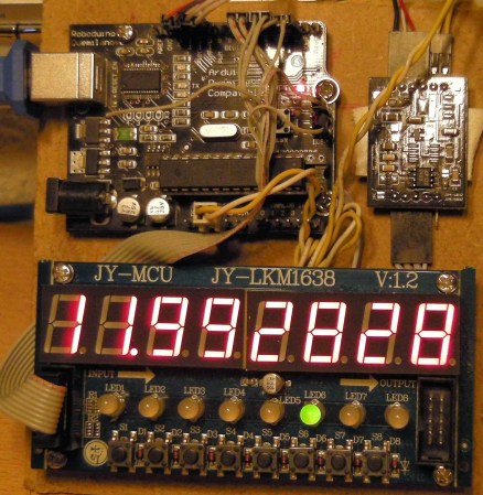
This collection of hardware is a diy voltmeter. It can measure up to 17V with 1 microvolt resolution while taking seven samples per second. The LTC2400 ADC board is used to make the measurements, with the Arduino processing the output and taking care of the display and user input buttons.

In addition to showing off what the thing can do in the video after the break, [Luis] gives us a look at the easter egg he added to the project. When you have a source that is very precisely 12V, the meter will read out Hackaday.com!

Incidentally the display used in this hack is one we’ve seen before. Obviously this is a convenient way to add interactive controls to your projects.


This is an entry in the Fubarino Contest for a chance at one of the 20 Fubarino SD boards which Microchip has put up as prizes!

Continue reading “Fubarino Contest: Micro Voltmeter”

Turning Cheap Voltmeters Into I2C Displays

Voltmeter I2C Displays

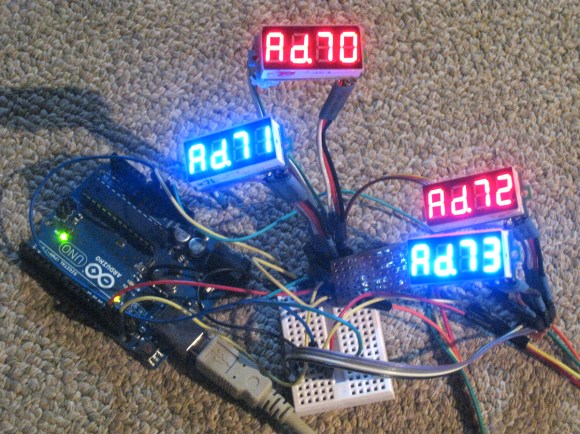
[Tom] needed 8 displays for a project. He wanted to to control them over I2C, and was trying to reduce cost. Some vendors make I2C controllable seven segment displays, but they cost about $10 each. [Tom] figured he could hack cheap voltmeters to get the same results for about $3 a pop.

The voltmeters that [Tom] bought used a 8 bit STM8S003F3P6 microcontroller. He reverse engineered the device and re-created the schematic to find out where the I2C and programming pins would be. Then he hooked it up to a STM8 Discovery development board, which has an integrated programmer.

With the hardware figured out, it was time for new firmware. Fortunately, [ba0sh1] had already written firmware for a similar purpose which could easily be adapted. The code implements a software I2C slave, which reads data off the bus and displays it. It’s all available on Github.

The end result is a I2C controlled display for a third of the cost. Next time you need a bunch of these in a project, consider picking up some cheap voltmeters.

Award Clock Put To Good Use As A Bench Meter

award-clock-turned-voltage-meter

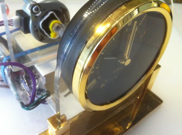
The motivation industry turns out these type of award trinkets by the millions. Here’s a way to actually put the thing to use. Instead of displaying time, the clock dial serves as the readout of a voltage meter.

When we first saw this post we assumed that the hack used some type of coil injection to drive the hands. But it turns out that this is mechanically driven. The image above shows the stepper motor which is mounted behind the clock. Its drive shaft is coupled with the adjustment knob on the back of the clock. The precision of the motor lets the PICAXE set the clock dial based on the number of motor steps. The hour hand shows the tens value with the minutes serving as ones (base 10, not base 60). This means the top measurable voltage is 12V — when the hour hand is at 12 the measurement is 0 volts plus tenths of a volt from the minute hand. With the dial taken care of the rest of the project focuses on measuring the voltage using the ADC, which has an upper limit of just 5V. This is overcome with a simple voltage divider.

After the break you can see the accuracy of the rig as it performs measurements next to a digital voltmeter.

Continue reading “Award Clock Put To Good Use As A Bench Meter”

$4 Volt Meter From A Dollar Store Pedometer

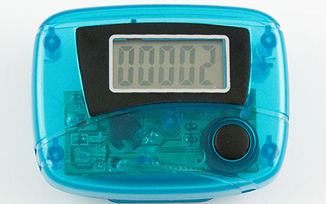
[Paulo]’s got a few solar panels on his shed, and while he does have a fairly nice setup with a battery charge controller, he found himself looking around for a panel voltmeter. Of course you can buy a panel voltmeter for under $20, but [Paulo] wanted something that fit his 4-4-4 plan; his voltmeter should cost under $4, draw less than 4mA, and last for 4 years. The jury is still out on the 4 year qualifier, but he did manage to meet his other goals by repurposing a dollar store pedometer as a voltmeter.

The pedometer in question is a very simple device. After inspecting the PCB, [Paulo] found it operates by looking at a trigger pin and incrementing the number on the display each time the circuit closed. [Paul] designed a very small PIC12F-powered circuit that reads the voltage of his batteries and triggers the pedometer’s LCD for every 10th of a volt. To display 12.6 Volts, [Paulo]’s code triggers the LCD 126 times, for example.

After wiring up the reset button so the display will go back down to zero for each new reading, [Paulo] encased his new volt meter in a plastic box. It’s not exactly a fast way of measuring voltage, but seeing as how that won’t change very fast, it’s the perfect solution for [Paulo]’s solar charger setup.

ultimate-breadboard

The Ultimate Breadboard – A Prototyping Station That Has It All

[Claudio] was working on a homebrew oscilloscope project when he started thinking about how unsuitable a standard breadboard is for a large-scale project. Rather than adding components on top of components until they became what he lovingly calls a “fragile, unforgiving crapstack”, he decided to build himself the Ultimate Breadboard.

He packed so much into his design, that it’s honestly hard to know where to begin describing it. Aside from an appropriately large breadboarding surface embedded in the center of the console, he added a power supply to the left hand side, which sits just below an Avr-Net-IO board. The right side of the console features an Arduino NG, and a pair of level converters. He also added some LED-based VU meters, a couple of 7-segment displays, an LCD display, an analog voltmeter, along with plenty of I/O connectors.

The Ultimate Breadboard might look a bit daunting at first, but it seems like an awesome setup on which to do any sort of prototyping. Be sure to check out the video below for more details and to see [Claudio] give a tour of the device.

Continue reading “The Ultimate Breadboard – A Prototyping Station That Has It All”