This Packable Ham Radio Antenna Is Made From Nothing But Tape

On today’s episode of “Will It Antenna?”, [Ben Eadie (VE6SFX)] designs and tests an antenna made entirely of tape, and spoiler alert — it works pretty well.

By way of background, the basic design [Ben] uses here is known as a J-pole, a popular “my first antenna” design for amateur radio operators looking to go beyond the stock whip antenna that comes with that cheap handy-talkie you just can’t resist buying as soon as you get your license. Usually, though, hams will build their J-poles from rigid materials, copper water pipe being a typical choice. Copper has the advantage of being easily sourced, and also results in a self-supporting, weather-resistant antenna that’s easy to mount outdoors. However, copper is getting to be egregiously expensive, and a couple of meters of water pipe isn’t exactly amenable to portable operation, if that’s your jam.

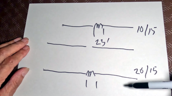
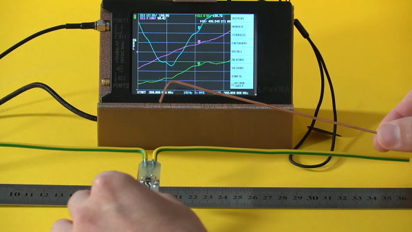
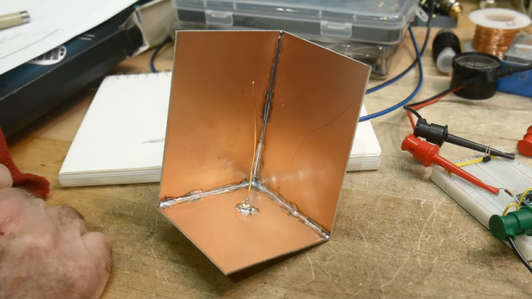
To solve those problems, [Ben] decided to keep his copper use to a minimum with a roll of copper foil tape. He doesn’t provide any specs on the tape, but it looks like it’s about 6 mm (1/4″) wide and judging by a quick Amazon search, probably goes for about $10 a roll. He starts the build with a couple of strips of plain old duck tape — we’ve already had the “duck vs. duct” argument — laid out with the sticky sides together. The copper foil is applied to the duck tape backing using dimensions from any of the J-pole calculators available online. Dimensions are critical to getting good performance from a J-pole, and this is where [Ben]’s tape design shines. Element too long? No problem, just peel up a bit and tear some off. Did you go too far and make an element too short? Easy — just stick on an extension piece of foil. Tuning the location of the feedline connection was a snap, too, with movable terminals held in place with magnets.

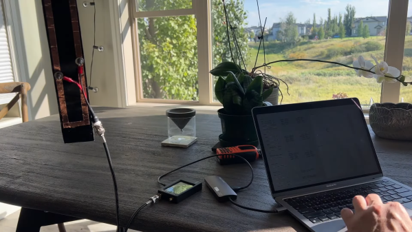
Once everything was tuned up, [Ben] soldered down the feed points and covered the foil with a protective layer of duck tape. The antenna performed swimmingly, and aside from costing almost nothing to build, it weighs very little, rolls up to fit in a pack for field operations, and can easily be hoisted into a tree for better coverage. Looks like we’ll be putting in an order for some copper tape and building one of these too. Continue reading “This Packable Ham Radio Antenna Is Made From Nothing But Tape”

Antennas Can Be A Total Mystery

The real action in the world of ham radio is generally in the high frequency bands. Despite the name, these are relatively low-frequency bands by modern standards and the antenna sizes can get a little extreme. After all, not everyone can put up an 80-meter dipole, but ham radio operators have come up with a number of interesting ways of getting on the air anyway. The only problem is that a lot of these antennas don’t seem as though they should work half as well as they do, and [MIKROWAVE1] takes a look back on some of the more exotic radiators.

He does note that for a new ham radio operator it’s best to keep it simple, beginning work with a dipole, but there are still a number of options to keep the size down. A few examples are given using helically-wound vertical antennas or antennas with tuned sections of coaxial cable. From there the more esoteric antennas are explored, such as underground antennas, complex loops and other ways of making a long wire fit in a small space, and even simpler designs like throwing a weight with a piece of wire attached out the window of an apartment building.

While antenna theory is certainly a good start for building antennas, a lot of the design of antennas strays into artistry and even folklore as various hams will have successes with certain types and others won’t. It’s not a one-size-fits-all situation so the important thing is to keep experimenting and try anything that comes to mind as long as it helps get on the air. A good starting point is [Dan Maloney]’s $50 Ham Guide series, and one piece specifically dealing with HF antennas.

Continue reading “Antennas Can Be A Total Mystery”

Ham Radio Mini Beam

Years ago, ham radio operators more often than not had land, and usually there weren’t any restrictions on what kind of antenna they could erect on that land. These days you are more likely to live with less or no land, and even if you do own property, you might have restrictions that prevent you from putting up any kind of visible antenna.

But even if that’s not the case, you might not have room for an old-fashioned “tri-bander” or “cubical quad” that the hams of old preferred. [Waters & Stanton] has a 65-year-old design for a miniature beam that he explains, and it produces a good beam antenna in a reduced amount of space. You can watch a video about the antenna below.

The design uses a doublet — a dipole fed with a balanced line and tuned at the feed point. A 22-foot doublet can cover 20 meters down to 10 meters without traps. Adding a director and reflector element provides directionality and gain. A unique arrangement allowed a 12-foot boom to support multiple elements on some bands by introducing a central coil on some elements. For example, the director is tuned to 15 meters using a center coil. But the coil is shorted with a 10 meter quarter stub that acts as a short on that band. You can see a complete explanation in the video.

We were hoping to see a build and some on-the-air testing, but, apparently, that is left as an exercise for the viewer. We imagine that 65 years ago, you’d use a grid dip oscillator to tune the stubs. Today, an antenna analyzer would do the job easily.

Continue reading “Ham Radio Mini Beam”

The Dipole Antenna Isn’t As Simple As It Appears

Dipole antennas are easy, right? Just follow the formula, cut two pieces of wire, attach your feedline, and you’re on the air.  But then again, maybe not. You’re always advised to cut the legs a little long so you can trim to the right length, but why? Shouldn’t the math just be right? And what difference does wire choice make on the antenna’s characteristics? The simple dipole isn’t really that simple at all.

If you’ve got antenna questions, check out [FesZ]’s new video on resonant dipoles, which is a deep dive into some of the mysteries of the humble dipole. In true [FesZ] fashion, he starts with simulations of various dipole configurations ranging from the ideal case — a lossless conductor in free space with as close to zero diameter conductors as the MMANA antenna simulator can support — and gradually build up to more practical designs. Continue reading “The Dipole Antenna Isn’t As Simple As It Appears”

Adding Smart Watch Features To Vintage Casio

[Matteo] has been a fan of the Casio F-91W wristwatch virtually since its release in 1989. And not without good reason, either. The watch boasts reliable timekeeping and extremely long battery life thanks to a modern quartz crystal and has just about every feature needed in a watch such as an alarm and a timer. And, since it’s been in use since the 80s, it’s also a device built to last. The only thing that’s really missing from it, at least as far as [Matteo] was concerned, was a contactless payment ability.

Contactless systems use near-field communication (NFC) to remotely power a small chip via a radio antenna when in close proximity. All that’s really required for a system like this is to figure out a way to get a chip and an antenna and to place them inside a new device. [Matteo] scavenges the chip from a payment card, but then builds a new antenna by hand in order to ensure that it fits into the smaller watch face. Using a NanoVNA as an antenna analyzer he is able to recreate the performance of the original antenna setup in the smaller form factor and verify everything works before sealing it all up in a 3D-printed enclosure that sandwiches the watch.

There are a few reasons why using a contactless payment system with a watch like this, instead of relying on a smartwatch, might be preferential. For one, [Matteo] hopes to explore the idea that one of the physical buttons on the watch could be used to physically disable the device to reduce pickpocketing risk if needed. It’s also good to not have to buy the latest high-dollar tech gadget just for conveniences like this too, but we’ve seen in the past that it’s not too hard just to get these systems out of their cards in the first place.

Headset’s Poor Range Fixed By Replacing Antenna

[rafii6312]’s Corsair HS80 wireless headset had a big problem: short range. The sound quality was great, but the wireless range wasn’t winning any friends. Fortunately, the solution was just to swap the small SMT antenna on the USB transmitter for an external one.

Original SMT antenna (blue component) offers small size, but poor range.

This particular headset relies on a USB dongle to transmit audio from PC to headset over its own 2.4 GHz wireless connection. By popping open the USB dongle, [rafii6312] was able to identify an SMT antenna and easily desolder it, replacing it with a wired connection to a spare 2.4 GHz external antenna. That’s all it took to boost the headset’s range from barely one room to easily three rooms, which is a success by any measure.

Sadly, the USB transmitter dongle doesn’t have any intention of being opened and puts up a fight, so the process was a bit destructive. No problem, [rafii6312] simply fired up Fusion360 to design a new 3D-printed enclosure that accommodated the new antenna. Pictures, instructions, and 3D model files are all available on the project page, if you want to improve your headset, too.

This kind of antenna upgrade is reasonably straightforward, but if one is armed with the right knowledge, antenna upgrades from scratch using scrap wire and dollar store hardware are entirely possible. Just be sure to pick an antenna that doesn’t weigh down your headset.

Cornering The Antenna Market

Sometimes antennas can seem like black magic. However, when you see things like a dish antenna, it sort of makes sense, right? Just like a mirror focuses light, the parabola of a dish focuses RF energy. But [IMSAI Guy] shows another common-sense antenna arrangement: a corner reflector dipole. He had built one years ago and decided to do a bit of research and make another one.

In a clever use of copper-clad board, he was able to make a reasonable reflector by soldering together three boards and an RF connector. A single wire makes the “driven element,” and by bending it to just the right position, you can change the characteristic impedance for matching.

The antenna, in this case, is essentially a quarter-wave antenna with a ground plane and reflector arrangement. After the obligatory chalk talk, he breaks out the vector network analyzer and shows how well it matches. He didn’t, however, measure the gain or directional selectivity due to the reflector.

Intuitively, you’d think this kind of antenna would be good for direction finding purposes. In fact, hams that use handy talkies for direction finding often use their bodies to block signals, much like these reflectors should.

The [IMSAI Guy] reflector is pretty small, but you can easily make bigger ones. Using PCB material for antennas isn’t anything new, either, but we still enjoyed this simple corner reflector build.

Continue reading “Cornering The Antenna Market”