Perfect Wire Hose Clamps With A Simple DIY Tool

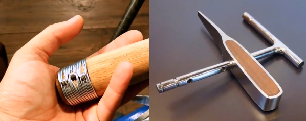
Hose clamps have been around as long as we’ve been using flexible hoses. Usually, a clamp consists of a slotted metal strap, and a screw for tightening. Most of us know how quickly they slip when you want to add a bit more torque, or the frustration of not having the right size. Fortunately [Max Egorov] reminded us of DIY wire clamps (video after the break), an excellent alternative that is very effective, covers an infinite size range and is easy to make with a simple tool.

The wire clamp is in effect a doubled girth hitch, that is pulled tight with the ends bent over to keep the tension. [Max] shows you how to easily make your own clamper tool with basic tools and a few bits of steel. Making it as ornate as his one is definitely not required.  You can also buy a commercial tool that is sold under the name ClampTite, which uses a leadscrew type design.

To achieve a tight seal with a hose clamp, the main requirement is constant pressure around its entire circumference. These wire clamps do this very well and are popular among aircraft mechanics, since flying in a plane with a leaky coolant or fuel hose could shorten your lifespan a bit. [Max] also demonstrates a variety of other uses for these including fixing tool handles and even building a ladder.

We love simple but effective tools like this, and we’ll definitely be adding one to our toolbox. Have you used these before? Let us know in the comments!

There is (almost) never such a thing as too many tools, and making your own is very satisfying. We’ve seen people build an outfit a complete carpentry workshop using plywood, and build sheet metal press brake with no welding.

Thanks [Keith O] for the tip!

Continue reading “Perfect Wire Hose Clamps With A Simple DIY Tool”

Precision DIY Calipers? That’s A Moiré!

Moiré patterns are a thing of art, physics, and now tool design! [Julldozer] from Mojoptix creatively uses a moiré pattern to achieve a 0.05 mm precision goal for his custom designed 3D printed calipers. His calipers are designed to validate a 3D print against the original 3D model. When choosing which calipers are best for a job, he points out two critical features to measure them up against, accuracy and precision which he explains the definition of in his informative video. The accuracy and precision values he sets as constraints for his own design are 0.5 mm and 0.05 mm respectively.

By experimenting with different parameters of a moiré pattern: the scale of one pattern in relation to the other, the distance of the black lines on both images, and the thickness of black and white lines. [Julldozer] discovers that the latter is the best way to amplify and translate a small linear movement to a standout visual for measurement. Using a Python script which he makes available, he generates images for the moiré pattern by increasing line thickness ratios 50:50 to 95:5, black to white creating triangular moiré fringes that point to 1/100th of a millimeter. The centimeter and millimeter measurements are indicated by a traditional ruler layout.

Looking for more tool hacks and builds? Check out how to prolong the battery life of a pair of digital calipers and how to build a tiny hot wire foam cutter.


Continue reading “Precision DIY Calipers? That’s A Moiré!”

3D Printering: Printing Sticks For A PLA Hot Glue Gun

When is a hot glue stick not a hot glue stick? When it’s PLA, of course! A glue gun that dispenses molten PLA instead of hot glue turned out to be a handy tool for joining 3D-printed objects together, once I had figured out how to print my own “glue” sticks out of PLA. The result is a bit like a plus-sized 3D-printing pen, but much simpler and capable of much heavier extrusion. But it wasn’t quite as simple as shoving scrap PLA into a hot glue gun and mashing the trigger; a few glitches needed to be ironed out.

Why Use a Glue Gun for PLA?

Some solutions come from no more than looking at two dissimilar things while in the right mindset, and realizing they can be mashed together. In this case I had recently segmented a large, hollow, 3D model into smaller 3D-printer-sized pieces and printed them all out, but found myself with a problem. I now had a large number of curved, thin-walled pieces that needed to be connected flush with one another. These were essentially butt joints on all sides — the weakest kind of joint — offering very little surface for gluing. On top of it all, the curved surfaces meant clamping was impractical, and any movement of the pieces while gluing would result in other pieces not lining up.

An advantage was that only the outside of my hollow model was a presentation surface; the inside could be ugly. A hot glue gun is worth considering for a job like this. The idea would be to hold two pieces with the presentation sides lined up properly with each other, then anchor the seams together by applying melted glue on the inside (non-presentation) side of the joint. Let the hot glue cool and harden, and repeat. It’s a workable process, but I felt that hot glue just wasn’t the right thing to use in this case. Hot glue can be slow to cool completely, and will always have a bit of flexibility to it. I wanted to work fast, and I wanted the joints to be hard and stiff. What I really wanted was melted PLA instead of glue, but I had no way to do it. Friction welding the 3D-printed pieces was a possibility but I doubted how maneuverable my rotary tool would be in awkward orientations. I was considering ordering a 3D-printing pen to use as a small PLA spot welder when I laid eyes on my cheap desktop glue gun.

Continue reading “3D Printering: Printing Sticks For A PLA Hot Glue Gun”

Roll Your Own Rotary Tool

Rotary tools are great little handheld powerhouses that fill the void between manual tools and larger shop machines. They’re also kind of expensive for what they are, which is essentially a power circuit, a switch, and a high-RPM motor with a tool coupling on the shaft. If your tooling needs are few and you have the resources, why not make your own?

[DIY King 00] built himself a cordless rotary tool for less than $10 out of commonly-available parts. It doesn’t run nearly as fast as commercial rotary tools, but that’s not necessarily a bad thing. He made the body out of 2″ diameter PVC and mounted a 12 V, 400 RPM DC motor directly to one of the fiberglass end caps. Tools are chucked into a collet that screws into a coupler on the motor shaft.

For power, [DIY King 00] built a 7.4 V battery pack by wiring two 18650 cells from an old laptop battery in series. It isn’t the full 12 V, but it’s enough power for light-duty work. These 2200 mAh cells should last a while and are rechargeable through the port mounted in the other end cap.

Drill down past the break to see the build video and watch the tool power through plywood, fiberglass, and inch-thick lumber. Once you’ve made your own rotary tool, try your hand at a DIY cordless soldering iron.

Continue reading “Roll Your Own Rotary Tool”

DIY Induction Soldering Iron

[Kasyan TV] shows us how to make a really simple DIY induction soldering iron complete with DIY soldering tips.

This is a pretty cool project. Most of us are used to temperature controlled ceramic heating elements, but there are other ways to get those irons up to temperature. Using scraps from older, presumably broken, soldering irons and some pieces of copper and iron along with a thermocouple for temperature management, [Kasyan TV] manages to throw together an Inductively heated soldering iron. To insulate the coil from the iron they use Kapton tape. The video goes on to show how to make your own induction iron, although missing is a power supply. We are sure a quick eBay search for an induction heater module should bring up something suitable to power the iron, or you could just wait and watch the their next video that will go over power supplies. The soldering tips are simply made from thick copper wire sculpted into the correct shape.

There are advantages to using a soldering iron like this, for example they are pretty durable and will take a knock or two, Our concern is that magnetically sensitive parts may not be happy, and the iron might destroy what you are trying to build. Either way we’ve put the video below the break, so take a look.

Hackaday has featured a few different DIY soldering irons and some pretty cool DIY Soldering Stations over the years. What is your soldering iron of choice and why?

Continue reading “DIY Induction Soldering Iron”

LED Tester Royale

What do you get for the geek who has everything and likes LEDs? A tricked-out LED tester, naturally. [Dave Cook]’s deluxe model sports an LCD screen and two adjustable values: desired current and supply voltage. Dial these in, plug in your LED, and the tiny electronic brain inside figures out the resistor value that you need. How easy is that?

An LED tester can be as easy as a constant-current power supply, and in fact that’s what [Dave]’s first LED tester was, in essence. Set an LM317 circuit up to output 10mA, say, and you can safely test out about any LED. Read off the operating voltage, subtract that from the supply voltage, and then divide by your desired current to figure out the required resistor. It only takes a few seconds, but that’s a few seconds too many!

The new device does the math for you by adding an AVR ATtiny84 into the mix. The microcontroller reads the voltage that the constant current supply requires, does the above-mentioned subtraction and division, and displays the needed resistor. So simple. And as he demonstrates in the video below, it does double-duty as a diode tester.

This is a great beginner’s project, and it introduces a bunch of fundamental ideas: reading the ADC, writing to an LED screen, building a constant current circuit, etc. And at the end, you have a useful tool. This would make a great kit!

Continue reading “LED Tester Royale”